Opel Frontera UE. Manual - part 845


  Index      Opel     Opel Frontera UE - service repair manual 1999-2001 year


Search            copyright infringement  


Content   ..  843  844  845  846   ..


Opel Frontera UE. Manual - part 845


6E1–263

X22SE 2.2L ENGINE DRIVEABILITY AND EMISSION

Camshaft Position (CMP)

 Sensor

Removal Procedure

1. Disconnect the negative battery cable.
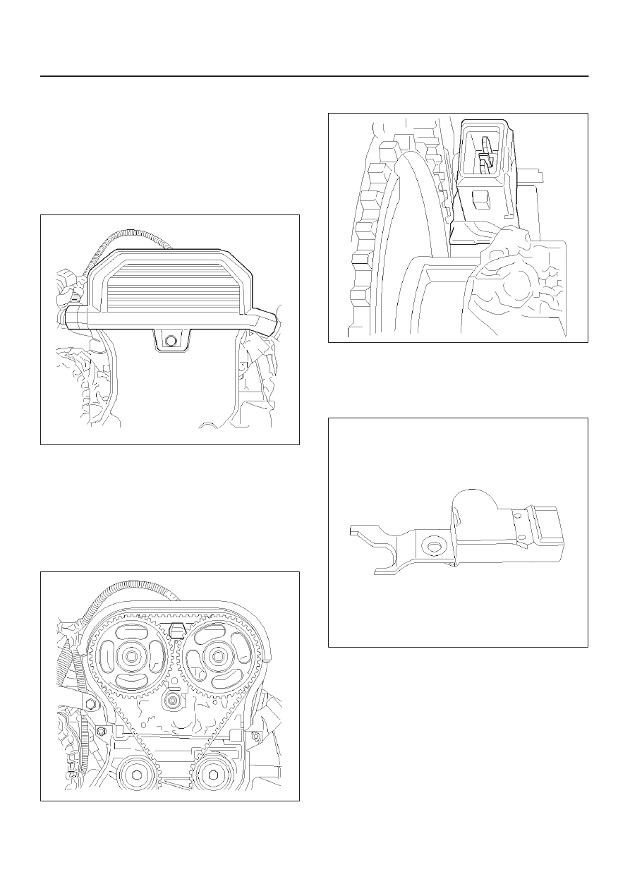
2. Remove spark plug cover on top of valve cover by

removing four retaining bolts.

3. Disconnect electrical connector from the sensor.

014RX003

4. Remove drive belt. Refer to Engine Mechanical

Section.

5. Remove top harness cover installed on timing belt

cover by removing a retaining screw.

6. Remove the retaining bolts holding crankshaft pulley,

and pull crankshaft pulley while wiggling. Refer to
Engine Mechanical Section.

7. Remove the retaining screws for timing belt cover and

timing belt cover.

014RX004

8. Remove the retaining bolt for the sensor and pull up

camshaft position sensor.

014RX005

Installation Procedure

1. Insert camshaft position sensor in position.
2. Install retaining bolt.

014RX007

3. Install the timing belt cover and the retaining screws.
4. Install the crank shaft pulley and the mounting bolts.

Holes for mounting bolts are off the pitch. The pulley
can be mounted only one way to install all mounting
bolts. Tighten the bolts. Refer to Engine Mechanical
section.

6E1–264

X22SE 2.2L ENGINE DRIVEABILITY AND EMISSION

5. Install the drive belt. Refer to Engine Mechanical

Section.

014RX005

6. Install the top harness cover onto timing belt cover.
7. Connect electrical connector to the sensor and

securely lock it.

8. Install the spark plug cover.
9. Connect the negative battery cable.

014RX004

Crankshaft Position (CKP) 

Sensor

Removal Procedure

1. Disconnect the negative battery cable.
2. Remove the drive belt. Refer to Engine Mechanical

Section.

014RX003

3. Remove the pwer steering pump and

mounting–bracket from engine. Refer to Engine
Mechanical Section.

4. Disconnect electrical connector from the sensor.

014RX006

6E1–265

X22SE 2.2L ENGINE DRIVEABILITY AND EMISSION

5. Remove the retaining bolt and sensor from the engine

block.

NOTE: Use caution to avoid any hot oil that might drip
out.

0013

Installation Procedure

1. Install the crank shaft position sensor to its position.
2. Install and tighten the mounting bolt. Refer to Engine

Mechanical Section.

0013

3. Reinstall the power steering pump and bracket to the

engine.

014RX006

4. Reinstall the accessory drive belt.
5. Connect the negative battery cable.

014RX003

6E1–266

X22SE 2.2L ENGINE DRIVEABILITY AND EMISSION

EEPROM

EEPROM

The Electronically Erasable Programmable Read Only
Memory (EEPROM) is a permanent memory that is
physically soldered within the ECM.  The EEPROM
contains program and calibration information that the
ECM needs to control Powertrain operation.

014RX002

901RX031

Functional Check

1. Perform the On–Board Diagnostic System Check.
2. Start the engine and run for least one minute.
3. Check for DTCs using Tech 2.
4. If the ECM fails to program, proceed as follow:

D

Ensure that all ECM connections are OK.

D

Check the ITCS for latest version software.

D

Attempt to program ECM again. If ECM still cannot
be programmed properly, replace ECM. The
replacement ECM must be programmed.

Engine Coolant Temperature

(ECT) Sensor

Removal Procedure

1. Disconnect the negative battery cable.
2. Drain enough engine coolant so that the coolant level

will be below the ECT sensor.

3. Remove electrical connector from the sensor located

on the intake manifold above the ignition coil.

4. Unscrew the sensor from the manifold.

014RX008

Installation Procedure

1. Install the sensor into the intake manifold. Do not over

tighten.

2. Connect electrical connector.


Content   ..  843  844  845  846   ..