Opel Frontera UE. Manual - part 817
6E1–151
X22SE 2.2L ENGINE DRIVEABILITY AND EMISSION
2. If the conditions for the test as described above are
met, a Diagnostic Trouble Code P0325 will set and
MIL will illuminate.
4. If the engine has an internal knock or audible noise
that causes a knocking type noise on the engine
block, the knock sensor may be responding to the
noise.
6. The Tech 2 displays knock sensor activity in counts,
approximately 20–50 at idle. The counts should
increase when engine speed is increased and the
counts should decrease when engine speed is
decreased.
7. Any circuitry, that is suspected as causing the
complaint, should be thoroughly checked for backed
out terminals, improper mating, broken locks,
improperly formed or damaged terminals, poor
terminal to wiring connections or physical damage
to the wiring harness.
8. If the KS module was previously replaced and the
Diagnostic Trouble Code resets, a malfunctioning
ECM is indicated.
9. Checking the internal resistance of the knock sensor
verifies if the knock sensor or the wiring to the
knock sensor is OK.
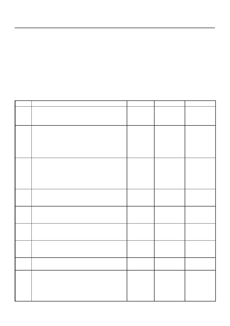
DTC P0325 KS Circuit Malfunction
Step
Action
Value(s)
Yes
No
1
Was the Powertrain ”On–Board Diagnostic (OBD)
System Check” performed?
—
—
Go to Step 2
Go to
Powertrain
OBD System
Check
2
1. Start the engine.
2. Install a Tech 2.
3. Clear the Diagnostic Trouble Codes.
4. Run the engine at slightly more than 10% throttle
angle.
Does the Malfunction Indicator Lamp (MIL) illuminate?
—
Go to Step 4
Go to Step 3
3
1. Turn the ignition switch ON, with engine OFF.
2. Review the Freeze Frame data and note the
parameters.
3. Operate the vehicle within the Conditions and
Conditions for Setting the DTC as noted.
Does the Malfunction Indicator Lamp (MIL) illuminate?
—
Go to Step 4
Go to Step
13
4
Listen to the engine while raising and lowering the
engine speed.
Is a knock or audible noise present?
—
Go to Step 5
Go to Step 6
5
Repair the mechanical engine problem or a loose
bracket or component.
Is the action complete?
—
Go to Step
13
—
6
Slowly increase the engine speed to the specified
value.
Does the KS Activity increase with the engine speed?
2500 RPM
Go to Step 7
Go to Step
11
7
Check for a poor connection at the ECM connector,
Knock sensor signal circuit and repair as necessary.
Was a repair necessary?
—
Go to Step
13
Go to Step 8
8
Replace the ECM.
Is the action complete?
—
Go to Step
13
—
9
1. Turn the ignition switch OFF.
2. Disconnect the ECM connectors at the ECM.
3. With a Digital Voltmeter (DVM) connected to
ground, measure the resistance of the knock
sensor through the knock sensor signal circuit.
Is the measured value within the specified value?
90K – 110K
W
Go to Step 7
Go to Step
10