Opel Frontera UE. Manual - part 811


  Index      Opel     Opel Frontera UE - service repair manual 1999-2001 year


Search            copyright infringement  


Content   ..  809  810  811  812   ..


Opel Frontera UE. Manual - part 811


6E1–127

X22SE 2.2L ENGINE DRIVEABILITY AND EMISSION

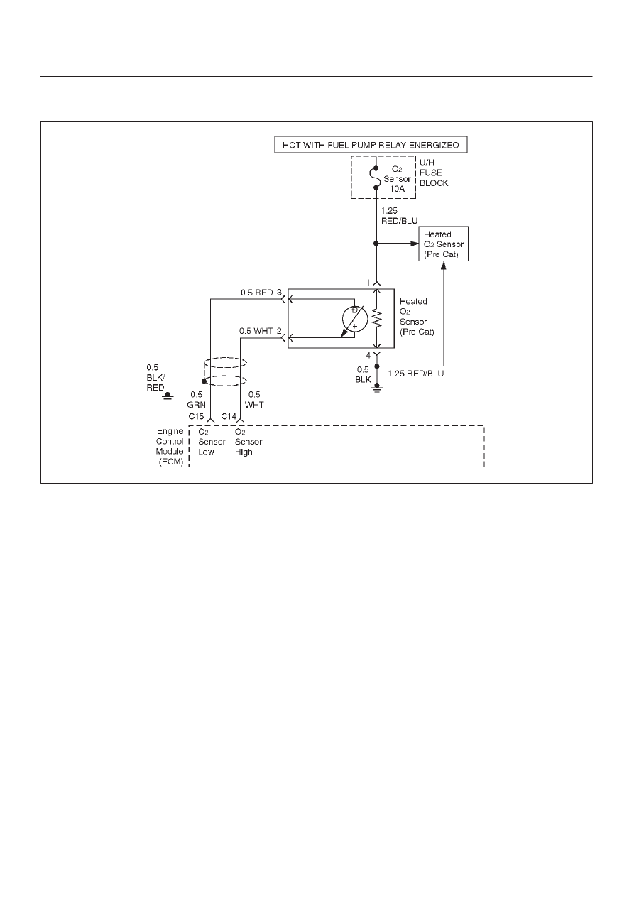
DIAGNOSTIC TROUBLE CODE (DTC) P0135 O2 SENSOR HEATER CIRCUIT

MALFUNCTION

D06RX119

Circuit Description

Heated oxygen sensors are used to minimize the amount
of time required for “Closed Loop” fuel control operation
and to allow accurate catalyst monitoring. The oxygen
sensor heater greatly decreases the amount of time
required for fuel control sensors Bank 1 HO2S 1.
The engine control module (ECM) will run the heater test
only after a cold start (determined by engine coolant and
intake air temperature at the time of start–up) and only
once during an ignition cycle. When the engine is started
the ECM will monitor the HO2S voltage. When the HO2S
voltage indicates a sufficiently active sensor, the ECM
looks at how much time has elapsed since start–up. If the
ECM determines that too much time was required for the
Bank 1 HO2S 1 to become active, a Diagnostic Trouble
Code P0135 will set.  DTC P0135 is a type B code.

Conditions for Setting the DTC

D

No related Diagnostic Trouble Codes.

D

Intake air temperature (IAT) is less than 32

°

C (90

°

F)

at start–up.

D

Engine coolant temperature (ECT) is less than 32

°

C

(90

°

F) at start–up.

D

IAT and ECT are within 5

°

C (9

°

F) of each other at

start–up.

D

Ignition voltage is between 11 and 16.6 V.

D

Average calculated air flow is less than 18 g/second
during sample period.

D

Throttle angle is less than 40%.

D

Bank 1 HO2S 1 voltage does not change more than
148 mV from the bias voltage (between 400 mV and
500 mV) for a longer amount of time than it should. The
maximum amount of time to come up to operating
range is 240 seconds. This warm–up time depends on
the engine coolant temperature at start–up and intake
air temperature at start–up.

Action Taken When the DTC Sets

D

The ECM will illuminate the malfunction indicator lamp
(MIL) after the second consecutive trip in which the
fault is detected.

D

The ECM will store conditions which were present
when the Diagnostic Trouble Code was set as Freeze
Frame and in the Failure Records data.

Conditions for Clearing the MIL/DTC

D

The ECM will turn the MIL OFF on the third consecutive
trip cycle during which the diagnostic has been run and
the fault condition is no longer present.

D

A history Diagnostic Trouble Code P0135 will clear
after 40 consecutive warm–up cycles have occurred
without a fault.

D

Diagnostic Trouble Code P0135 can be cleared by
using the Scan Tool’s ”Clear Info” function.

6E1–128

X22SE 2.2L ENGINE DRIVEABILITY AND EMISSION

Diagnostic Aids

Check for the following conditions:

D

Poor connection at ECM – Inspect harness connectors
for backed–out terminals, improper mating, broken
locks, improperly formed or damaged terminals, and
poor terminal–to–wire connection.

D

Damaged harness – Inspect the wiring harness for
damage; shorts to ground, shorts to battery positive
and open circuits. If the harness appears to be OK,
observe the ECT display on the Tech 2 while moving
connectors and wiring harnesses related to the sensor.
A change in the display will indicate the location of the
fault.

Reviewing the Failure Records vehicle mileage since the
diagnostic test last failed may help determine how often
the condition that caused the Diagnostic Trouble Code to
be set occurs. This may assist in diagnosing the
condition.

Test Description

Number(s) below refer to the step number(s) on the
Diagnostic Chart:

2. The HO2S should be allowed to cool before

performing this test. If the HO2S heater is
functioning, the signal voltage will gradually increase
or decrease as the sensor element warms. If the
heater is not functioning, the HO2S signal will
remain near the 450 mV bias voltage.

 4. Ensures that the ignition feed circuit to the HO2S is

not open or shorted. The test light should be
connected to a good chassis ground, in case the
HO2S low or HO2s heater ground circuit is faulty.

5. Checks the HO2S heater ground circuit.

6. Checks for an open or shorted HO2S heater

element.

10.An open HO2S signal or low circuit can cause the

HO2S heater to appear faulty. Check these circuits
before replacing the sensor.

DTC P0135 – O2 Sensor Heater Circuit Malfunction


Step

Action

Value(s)

Yes

No

1

Was the ”On–Board Diagnostic (OBD) System Check”
performed?

Go to Step 2 

Go to OBD

System

Check 

2

NOTE: If the engine has just been operating, allow
engine to cool for about one half hour before
proceeding.

1. Ignition OFF, engine OFF.
2. Install a Tech 2.
3. Ignition ON engine OFF monitor the Bank 1 HO2S 1

voltage.

Does the HO2S voltage go from bias voltage to above
and below the specified values?

Above 650

mV or below

250 mV

Refer to

Diagnostic

Aids 

Go to Step 3 

3

Inspect the fuse for the Bank 1 HO2S 1 ignition feed.

Is the fuse open?

Go to Step 15

Go to Step 4 

4

1. Ignition OFF.
2. Raise the vehicle.
3. Disconnect the Bank 1 HO2S 1 electrical connector.
4. Using a test light connected to a good ground (do

not use Bank 1 HO2S 1 heater ground or Bank 1
HO2S 1 low), probe the ignition feed circuit at the
Bank 1 HO2S 1 electrical connector (ECM harness
side).

Does the test light illuminate?

Go to Step 5 

Go to Step 7 

5

Connect the test light between the Bank 1 HO2S 1
ignition feed and the Bank 1 HO2S 1 heater ground.

Does the test light illuminate?

Go to Step 6 

Go to Step 8 

6E1–129

X22SE 2.2L ENGINE DRIVEABILITY AND EMISSION

DTC P0135 – O2 Sensor Heater Circuit Malfunction

  (Cont'd)

Step

No

Yes

Value(s)

Action

6

1. Allow the HO2S to cool for at least 10 minutes.
2. Using a Digital Voltmeter (DVM), measure the

resistance between the Bank 1 HO2S 1 ignition
feed and the Bank 1 HO2S 1 heater ground at the
Bank 1 HO2S 1 pigtail.

Is the HO2S heater resistance within the specified
values?

3–6 ohms

Go to Step 9 

Go to Step 10

7

Repair the open Bank 1 HO2S 1 ignition feed circuit to
Bank 1 HO2S 1.

Is the action complete?

Verify repair

8

Repair the open Bank 1 HO2S 1 heater ground circuit
to Bank 1 HO2S 1.

Is the action complete?

Verify repair

9

1. Check for a poor connection at the Bank 1 HO2S 1

harness terminals.

2. If a poor connection is found, replace terminals.

Was a poor connection found?

Verify repair

Go to Step 10

10

Check for a poor Bank 1 HO2S 1 high or low circuit
terminal connection at the Bank 1 HO2S 1 harness
connector and replace terminal(s) if necessary.

Did any terminals require replacement?

Verify repair

Go to Step 11

11

1. Ignition OFF.
2. Disconnect the ECM and check the continuity of the

Bank 1 HO2S 1 signal circuit and the Bank 1 HO2S
1 low circuit.

3. If the Bank 1 HO2S 1 high circuit or HO2S low circuit

measures over 5 

W

, repair open or poor connection

as necessary.

Was a problem found?

Verify repair

Go to Step 12

12

Check for a poor Bank 1 HO2S 1 low circuit terminal
connection at the ECM and replace the terminal if
necessary.

Did the terminal require replacement?

Verify repair

Go to Step 13

13

Check for a poor Bank 1 HO2S 1 high circuit terminal
connection at the ECM and replace the terminal if
necessary.

Did the terminal require replacement?

Verify repair

Go to Step 14

14

Replace the Bank 1 HO2S 1.

Is the action complete?

Verify repair

15

Locate and repair the short to ground in Bank 1 HO2S 1
ignition feed circuit and replace the fault fuse.

Is the action complete?

Verify repair

6E1–130

X22SE 2.2L ENGINE DRIVEABILITY AND EMISSION

DIAGNOSTIC TROUBLE CODE (DTC) P0171  SYSTEM TOO LEAN (BANK 1)

D06RX119

Circuit Description

To provide the best possible combination of driveability,
fuel economy, and emission control, a ”Closed Loop”
air/fuel metering system is used. While in ”Closed Loop”,
the engine control module (ECM) monitors the Bank 1
HO2S 1 signal and adjusts fuel delivery based upon the
HO2S signal voltage. A change made to fuel delivery will
be indicated by the long and short term fuel trim values
which can be monitored with a Tech 2. Ideal fuel trim
values are around 0%; if the HO2S signal indicates a lean
condition the ECM will add fuel, resulting in fuel trim
values above 0%. If a rich condition is detected, the fuel
trim values will be below 0%, indicating that the ECM is
reducing the amount of fuel delivered. If an excessively
lean condition is detected on Bank 1, the ECM will set
Diagnostic Trouble Code P0171.  DTC P0171 is a type B
code.
The ECM’s maximum authority to control long term fuel
trim allows a range between –14% and +20%. The ECM
monitors fuel trim under various engine speed/load fuel
trim cells before determining the status of the fuel trim
diagnostic.

Conditions for Setting the DTC

D

No Tech 2 test is being run.

D

None of the following: EGR Diagnostic Trouble Codes,
HO2S Diagnostic Trouble Codes, (response,
transition, open, low volts, no activity), TP sensor
Diagnostic Trouble Codes, MAP Diagnostic Trouble

Codes, IAT Diagnostic Trouble Codes, canister purge
Diagnostic Trouble Codes, EVAP Diagnostic Trouble
Codes, injector circuit Diagnostic Trouble Codes, or
misfire Diagnostic Trouble Codes.

D

Engine coolant temperature is between 65

°

C (149

°

F)

and 104

°

C (219

°

F).

D

Intake air temperature is between –40

°

C (–40

°

F) and

120

°

C (248

°

F).

D

Manifold absolute pressure is between 23.75 kPa and
99 kPa.

D

Engine speed is between 400 and 6000 RPM.

D

Barometric pressure is greater than 72.3 kPa.

D

System voltage is greater than 9.5v.

D

Engine is operating in ”Closed Loop”.

D

The average of the short term fuel trim samples is
greater than 0.97 and the average of adaptive index
multiplier samples is greater than 1.21.

Action Taken When the DTC Sets

D

The ECM will illuminate the malfunction indicator lamp
(MIL) after the second consecutive trip in which the
fault is detected.

D

The ECM will store conditions which were present
when the Diagnostic Trouble Code was set as Freeze
Frame and in the Failure Records data.


Content   ..  809  810  811  812   ..