Opel Frontera UE. Manual - part 784
6E1–19
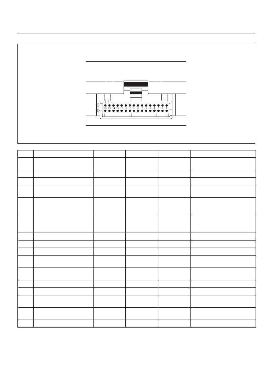
X22SE 2.2L ENGINE DRIVEABILITY AND EMISSION
ECM Pinout Table, 32–Pin White Connector – Row ”C”
TS23345
PIN
PIN Function
Wire Color
IGN ON
ENG RUN
Refer To
C1
Injector Cylinder #2
GRN/RED
B+ Varies
B+ Varies
General Description and
Operation, Fuel Injector
C2
Not Used
—
—
—
—
C3
Not Used
—
—
—
—
C4
Ignition Control Module
(ICM) Input
RED
0.0 V
0.1 V
General Description and
Operation, Fuel Injector
C5
Crankshaft Position (CKP)
Sensor Low
BLUE
4.98 V
0.76 V
(at idle)
General Description and
Operation, Crankshaft
Position Sensor
C6
Crankshaft Position
Sensor (CKP) High
GRN
5V
5V
General Description and
Operation, Crankshaft
Position Sensor
C7
ECM Ground
BLK/BLU
0.0 V
0.0 V
Chassis Electrical
C8
ECM Ground
BLK/BLU
0.0 V
0.0 V
Chassis Electrical
C9
ECM Ground
BLK/BLU
0.0 V
0.0 V
Chassis Electrical
C10
Tachometer Signal
BLK/RED
—
—
General Description and
Operation
C11
Fuel Gauge PWM Output
YEL/RED
Varies with
Fuel Level
Varies with
Fuel Level
General Description and
Operation
C12
High Fan Relay Control
RED/YEL
10.5 V
B+
Chassis Electrical
C13
Low Fan Relay Control
RED/BLU
—
—
Chassis Electrical
C14
Bank 1 HO2S 1 High
WHT
0.3 V
–0.1 to 1.1 V
General Description and
Operation, Fuel HO2S 1
C15
Bank 1 HO2S 1 Low
RED
0.0 V
0.1 V
General Description and
Operation, Fuel HO2S 1
C16
Not Used
—
—
—
—