Opel Frontera UE. Manual - part 775


  Index      Opel     Opel Frontera UE - service repair manual 1999-2001 year


Search            copyright infringement  


Content   ..  773  774  775  776   ..


Opel Frontera UE. Manual - part 775


IGNITION SYSTEM (X22SE 2.2L)

6D2–3

Possible causes:

• Too lean mixture

• Improper heat  value

Measuring Insulation Resistance

• Measure insulation resistance using a 500 volt 

megaohm meter.

• Replace spark plugs if measured value is out of 

standard.

Insulation resistance: 50 M

 or more

011RS010

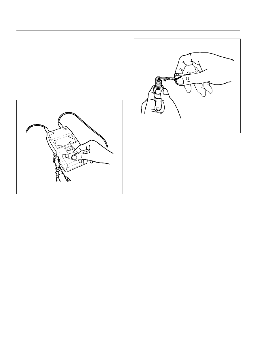
Cleaning Spark Plugs

• Clean spark plugs with a spark plug cleaner.

• Raise the ground electrode to an angle of 45 to 60 

degrees. if electrode is wet,dry it before cleaning.

• After spark plug is thoroughly cleaned,check insulator 

for presence of cracks.

• Clean threads and metal body with a wire brush.

• File the electrode tip if electrode is extremely worn.

• Bend the ground electrode to adjust the spark plug 

gap.

011RS011

Installation

1. Spark plugs

• Tighten spark plugs to the specified torque.

Torque: 25 N·m (2.5 kg·m/18 lb ft)

6D2–4

IGNITION SYSTEM (X22SE 2.2L)

Crankshaft Angle Sensor

Removal

1. Disconnect battery ground cable

2. Wiring connector from crankshaft angle sensor.

3. Remove crankshaft angle sensor from cylinder 

block.

015RW021

Installation

1. Install crankshaft angle sensor into the cylinder 

block.
Before installation,apply small amount of engine oil 
to the O–ring.

Torque: 6 N·m (0.6 kg·m/4 lb ft)

2. Reconnect wiring connector to crankshaft angle 

sensor.

IGNITION SYSTEM (X22SE 2.2L)

6D2–5

Main Data and Specifications

General Specifications

Ignition System

Ignition Form

Electronic Ignition System (El system) with Crankshaft angle Sensor

Spark Plug

Type

Electronic Spark Control

No. of Coils and Type

2 Solid State

Coil Location

Engine–mounted

Torque

20 N·m (2.0 kg·m/14 lb ft)

STARTING AND CHARGING SYSTEM (X22SE 2.2L)

6D3–1

ENGINE

STARTING AND CHARGING SYSTEM (X22SE 2.2L)

CONTENTS

Service Precaution......................................... 6D3 - 1

Starting System ............................................. 6D3 - 2

General Description ....................................... 6D3 - 2
Diagnosis ....................................................... 6D3 - 2

Starter ........................................................... 6D3 - 3

Removal ..................................................... 6D3 - 3
Installation .................................................. 6D3 - 3
Disassembled View .................................... 6D3 - 4
Inspection and Repair................................. 6D3 - 5
Characteristic Test...................................... 6D3 - 6

Charging System........................................... 6D3 - 7

General Description ....................................... 6D3 - 7
General On–Vehicle Inspection ..................... 6D3 - 7

Generator ...................................................... 6D3 - 9

Removal...................................................... 6D3 - 9
Inspection ................................................... 6D3 - 9
Installation................................................... 6D3 - 10
Disassembly ............................................... 6D3 - 10
Inspection and Repair................................. 6D3 - 12
Reassembly ................................................ 6D3 - 14

Main Data and Specifications ........................ 6D3 - 15

Service Precaution

WARNING:  THIS VEHICLE HAS A SUPPLEMENTAL
RESTRAINT SYSTEM (SRS).   REFER TO THE SRS
COMPONENT AND WIRING LOCATION VIEW IN
ORDER TO DETERMINE WHETHER  YOU ARE
PERFORMING SERVICE ON OR NEAR THE SRS
COMPONENTS OR THE SRS WIRING.  WHEN YOU
ARE PERFORMING SERVICE ON OR NEAR THE
SRS COMPONENTS OR THE SRS WIRING,  REFER
TO THE SRS SERVICE INFORMATION. FAILURE TO
FOLLOW WARNINGS COULD RESULT  IN
POSSIBLE AIR BAG DEPLOYMENT, PERSONAL
INJURY, OR OTHERWISE UNNEEDED SRS SYSTEM
REPAIRS.

CAUTION:  Always use the correct fastener in the
proper location.  When you replace a fastener, use
ONLY the exact part number for that application.
ISUZU will  call out those fasteners that require a
replacement after removal. ISUZU will also call out
the  fasteners that require thread lockers or thread
sealant. UNLESS OTHERWISE SPECIFIED, do  not
use supplemental coatings (Paints, greases, or
other corrosion inhibitors) on threaded  fasteners or
fastener joint interfaces. Generally, such coatings
adversely affect the fastener  torque and the joint
clamping force, and may damage the fastener. When
you install fasteners,  use the correct tightening
sequence and specifications. Following these
instructions can help you  avoid damage to parts
and systems.

SECTION


Content   ..  773  774  775  776   ..