Opel Frontera UE. Manual - part 662


  Index      Opel     Opel Frontera UE - service repair manual 1999-2001 year


Search            


Content   ..  660  661  662  663   ..


Opel Frontera UE. Manual - part 662


3C–12

FRONT SUSPENSION

2. Apply multipurpose type grease to the thrust 

washer,  and install washer with chamfered side 
facing knuckle. 

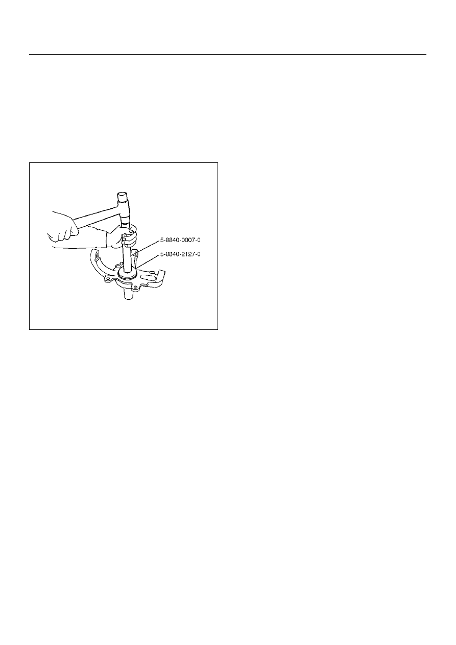
3. Use a new oil seal, and apply multipurpose type 

grease to the area surrounded by the lip (approx. 2 
g). Then use installer 5–8840–2127–0 and grip 5–
8840–0007–0 to install oil seal.  After fitting the oil 
seal to the installer,  drive it to the knuckle using a 
hammer or bench press until the tool front face 
contacts with the thrust washer.

901RW274

4. Install knuckle assembly.

5. Install upper ball joint and tighten the nut to the 

specified torque,  with just enough additional torque 
to align cotter pin holes. Install new cotter pin.

Torque: 98N·m (10.0kg·m/72lbft)

6. Install lower ball joint and tighten the nut to the 

specified torque,  with just enough additional torque 
to align cotter pin holes. Install new cotter pin.

Torque: 147N·m (15.0kg·m/lbft)

7. Install back plate.

8. Install wheel speed sensor.

9. Install torsion bar, refer to Torsion Bar in this section. 

NOTE:  Adjust the trim height. Refer to Front End 
Alignment Inspection and Adjustment  in Steering.

FRONT SUSPENSION

3C–13

Upper Control Arm

Upper Control Arm and Associated Parts

450RW005

Legend

EndOFCallout

Removal

1. Raise the vehicle and support the frame with 

suitable safety stands.

2. Remove wheel and tire assembly. Refer to Wheel in 

this section.

3. Remove the brake caliper and disconnect brake 

pipe. Refer to Disc Brakes in Brake section.

4. Support lower control arm with a jack. 

5. Remove speed sensor cable.

6. Remove nut and cotter pin then remove knuckle 

using remover 5–8840–2121–0.

(1) Bolt and Plate
(2) Camber Shims
(3) Caster Shims
(4) Nut Assembly
(5) Upper Control Arm Assembly
(6) Fulcrum Pin

(7) Bushing
(8) Plate
(9) Nut

(10) Speed Sensor Cable
(11) Nut and Cotter Pin
(12) Upper Ball Joint

3C–14

FRONT SUSPENSION

CAUTION:  Be careful not to damage the ball joint 
boot.

901RW273

7. Remove upper ball joint.

8. Remove bolt and plate.

9. Remove nut assembly.

10. Remove camber shims and note the positions and 

number of shims.

11. Remove caster shims and note the positions and 

number of shims.

12. Remove upper control arm assembly.

13. Remove nut.

14. Remove plate.

15. Remove bushing by using remover 5–8840–0256–0.

901RW277

901RW276

16. Remove fulcrum pin.

Inspection and Repair

Make necessary parts replacement if wear, damage, 
corrosion or any other abnormal conditions are found 
through inspection.
Check the following parts:

• Upper control arm

• Bushing

• Fulcrum pin 

Installation

1. Install fulcrum pin.

2. Install bushing by using installer 5–8840–0256–0 

and 5–8840–2307–0.

901RW278

FRONT SUSPENSION

3C–15

901RW279

3. Install plate.

4. Install nut and tighten fulcrum pin nut finger–tight.

NOTE:  Torque fulcrum pin nut after adjusting buffer 
clearance.

Buffer clearance: 22mm (0.87in)

Torque: 108N·m (11.0kg·m/80 lbft)

450RS012

5. Install upper control arm assembly with the fulcrum 

pin projections turned inward.

450RS013

Legend

EndOFCallout

6. Install the caster shims(2) between the chassis 

frame and fulcrum pin. 

7. Install the camber shims(1) between the chassis 

frame and fulcrum pin.

450RS014

(1) Projection
(2) Outward


Content   ..  660  661  662  663   ..