Opel Frontera UE. Manual - part 614
HEATING, VENTILATION AND AIR CONDITIONING (HVAC)
1A–13
Individual Inspection
Blower Motor
1. Disconnect the blower motor (B-5) connector from
the blower motor.
2. Connect the battery positive terminal to the No. 2
terminal of the blower motor and the negative to the
No. 1.
3. Be sure to check to see if the blower motor operates
correctly.
873RW008
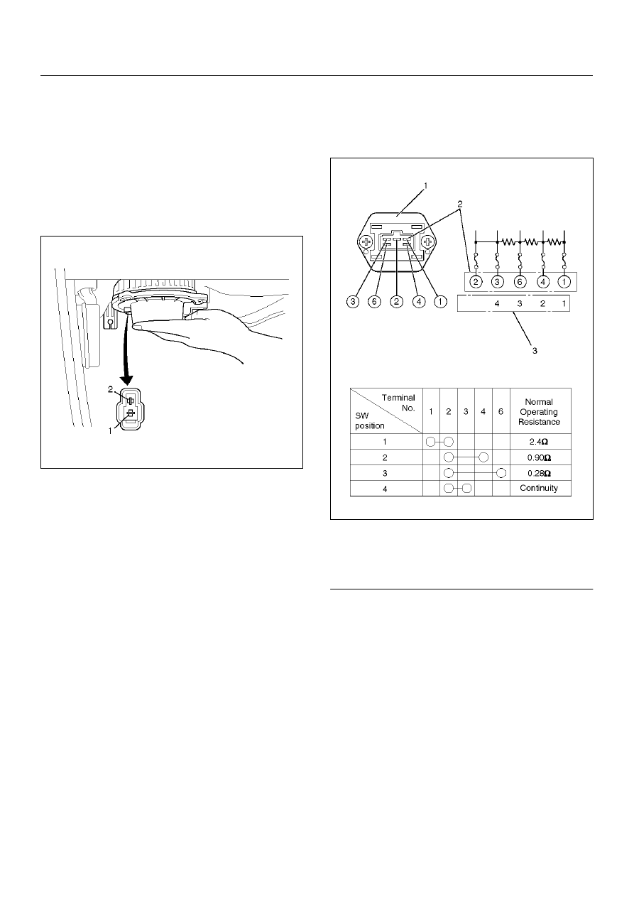
Resistor
1. Disconnect the resistor (B-3) connector.
2. Check for continuity and resistance between the
terminals of the resistor.
840RX013
EndOFCallout
Legend
(1) Resister Assembly
(2) Connector Terminal (Resister Side)
(3) Position Switch