Opel Frontera UE. Manual - part 613


  Index      Opel     Opel Frontera UE - service repair manual 1999-2001 year


Search            


Content   ..  611  612  613  614   ..


Opel Frontera UE. Manual - part 613


HEATING, VENTILATION AND AIR CONDITIONING (HVAC)

1A–9

Diagnosis

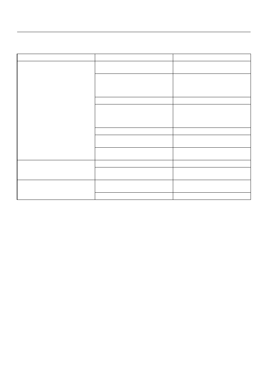
Heating Cycle diagnosis

Condition

Possible cause

Correction

No heating or insufficient heating.

Blower  motor  does  not  run  or  runs
improperly.

Refer to “FAN CONTROL LEVER
(FAN SWITCH) DIAGNOSIS".

Engine coolant temperature is low.

Check 

the 

engine 

coolant

temperature after warming up the
engine and check the     thermostat.
Replace as necessary.

Insufficient engine coolant.

Add engine coolant as required.

Circulation volume of engine coolant
is insufficient.

Check if the water hose to the
heater core is clogged, collapsed or
twisted. Repair or replace as
necessary.

Heater core clogged or collapsed.

Clean or replace as necessary.

The heater cores is not provided
with air sent from the blower motor.

Repair the temperature control link
unit or mode doors.

Duct connections defective or
unsealing.

Repair or replace as necessary.

Control lever moves but mode door
does not operate.

Cable attaching clip is not correct.

Repair

Link unit of heater or blower
assembly defective.

Repair

The mode door cannot be set to the
mode selected.

Link unit of heater unit or blower
assembly defective.

Repair.

Control cable is not adjusted.

Adjust.

1A–10

HEATING, VENTILATION AND AIR CONDITIONING (HVAC)

Fan Control Lever (Fan Switch) Diagnosis

Current flows to the blower motor through the heater
relay (X-6) to activate the rotation of the blower motor by
turning “ON" the fan control knob (fan switch). Blower
motor speed is controlled in stages by the resistor, by
operating the switch from “LOW" to “HIGH".
For the inspection of the relays, switches and units in
each table, refer to “INDIVIDUAL INSPECTION" in this
section.

D08RX250

Condition

Possible cause

Correction

Blower motor does not run.

Refer to Chart A

Blower motor does not run in certain
position (s).

Refer to Chart B, C, D and E

Blower motor does not stop at “OFF"
position.

Refer to Chart F

HEATING, VENTILATION AND AIR CONDITIONING (HVAC)

1A–11

Chart “A" Blower Motor Does Not Run

Chart “B" Blower Motor Does Not Run At Low Position

Chart “C" Blower Motor Does Not Run At Medium Low Position

Chart “D" Blower Motor Does Not Run At Medium High Position

Step

Action

Yes

No

Is relay (X-6) OK?

Go to Step 2

Replace

Is fuse F-4 (20A) OK?

Go to Step 3

Replace

Is resistor OK?

Go to Step 4

Replace

Is fan control lever OK?

Go to Step 5

Replace control 

lever assembly.

Is blower motor OK?

Go to Step 6

Replace

1. Turn the ignition switch “ON".

2. Turn fan control lever “ON".

3. Check to see if battery voltage is present at chassis side

connector terminal No. B5-2

Is there a battery voltage?

Poor ground or 

open circuit either 

between chassis 

side connector 

terminal No. B5-1 

and No. B3-2 or 

No. I23-1 and body 

ground (No. B-8).

Open circuit 

between No. F-4 

(20A) fuse and No. 

B5-2.

Step

Action

Yes

No

Is resistor OK?

Go to Step 2

Replace

Is fan control lever (Fan Switch) OK?

Open circuit 

between chassis 

side connector 

terminal No. B3-1 

and No.I23-2.

Replace control 

lever assembly.

Step

Action

Yes

No

Is resistor OK?

Go to Step 2

Replace

Is fan control lever (Fan Switch) OK?

Open circuit 

between the 
chassis side 

connector terminal     

No. B3-4 and No. 

I23-3.

Replace control 

lever assembly.

Step

Action

Yes

No

Is resistor OK?

Go to Step 2

Replace

Is fan control lever (Fan Switch) OK?

Open circuit 

between chassis 

side connector 

terminal No. B3-6 

and No. I23-4.

Replace control 

lever assembly.

1A–12

HEATING, VENTILATION AND AIR CONDITIONING (HVAC)

Chart “E" Blower Motor Does Not Run At High Position

Chart “F" Blower Motor Does Not Stop In The “OFF" Position   

Step

Action

Yes

No

Is resistor OK?

Go to Step 2

Replace

Is fan control lever (Fan Switch) OK?

Open circuit 

between Chassis 

side connector 

terminal No. B3-3 

and No. I23-5.

Replace control 

lever assembly.

Step

Action

Yes

No

Is the fan control lever (Fan Switch) OK?

Short circuit 

between chassis 

side connector 

terminal No.B5-1 

and 

No.B3-2,No.B3-3 

and No.I23-5, 

No.B3-6 and 

No.I23-4, No.B3-4 

and No.I23-3 or 

No.B3-1 and 

No.I23-2

Replace control 

lever assembly.


Content   ..  611  612  613  614   ..