Opel Frontera UE. Manual - part 583
9J–28
SUPPLEMENTAL RESTRAINT SYSTEM
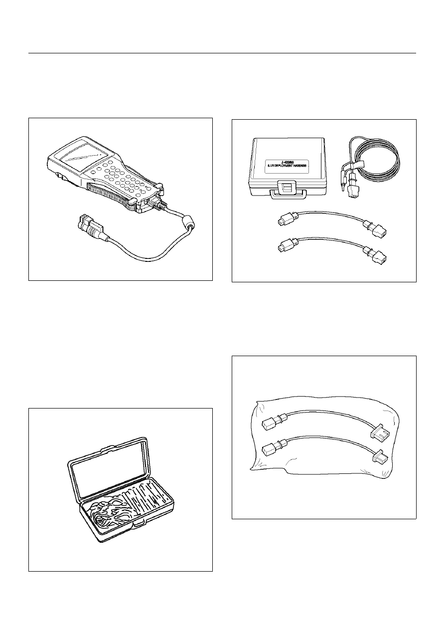
Scan Tool
The Tech 2 is used to read and clear SRS Diagnostic
Trouble Codes (DTCs). Refer to the Tech 2 Operator's
Manual for specific information on how to use the Tech
2.
901RW176
5–8840–0385–0 (J–35616–A) Connector
Test Adapter Kit
The 5–8840–0385–0 Connector Test Adapter Kit must
be used whenever a diagnostic procedure requests
checking or probing a terminal. Using the appropriate
adapter will ensure that no damage to the terminal will
occur from the Digital Multimeter (DVM) prove, such as
spreading or bending. The adapter will also give an
idea of whether contact tension is sufficient, helping to
find an open or intermittent open due to poor terminal
contact.
901RS151
5–8840–2468–0 (J–42986) SRS Deployment
Tool
The 5–8840–2468–0 Supplemental Restraint System
(SRS) Deployment Tool must be used for deployment of
the undeployed air bag.
901RX046
5–8840–2429–0 (J–42987) SRS Adapter For
Load Tool
The J–42987 SRS Adapter be used for connect
previous load tool to new SRS system when inspect
SRS system harness.
901RW107