Index Opel Opel Frontera UE - service repair manual 1999-2001 year
Search
Content .. 574 575 576 577 ..
Opel Frontera UE. Manual - part 576
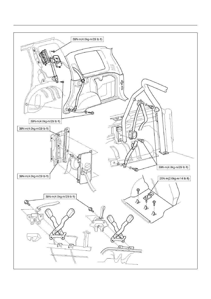
SEAT BELT SYSTEM
9A–15
755RX026