Opel Frontera UE. Manual - part 537
8F–8
BODY STRUCTURE
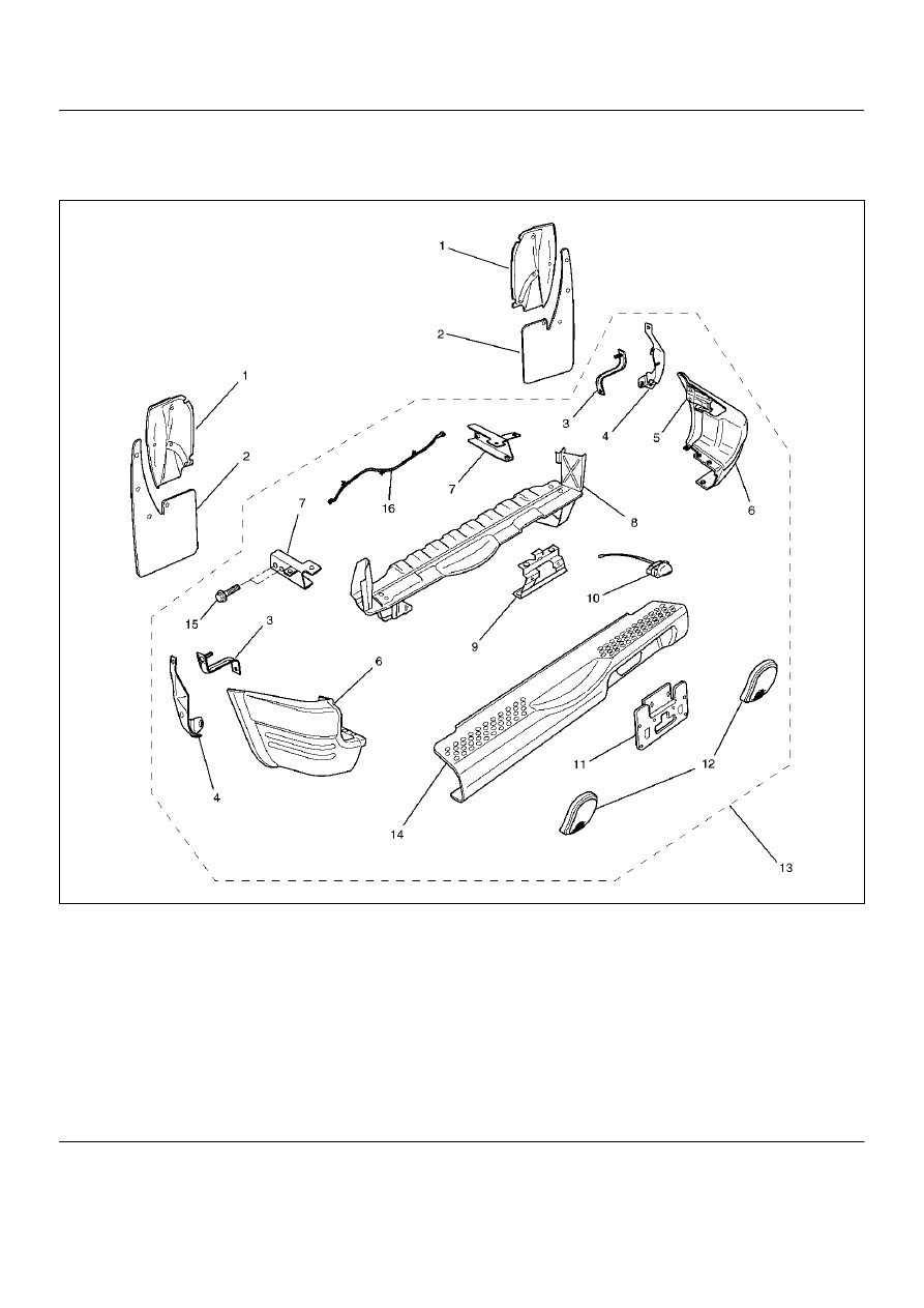
Rear Bumper
Parts Location
690RX002
Legend
EndOFCallout
(1) Protector
(2) Rear Mud Flap
(3) Bumper Bracket
(4) Rear Bumper Support
(5) Rear Bumper Slider Bracket
(6) Rear Corner Bumper
(7) Backber
(8) Rear Bumper Reinforcement Assembly
(9) Rear License Plate Bracket
(10) License Plate Light Assembly
(11) Rear License Plate Extension
(12) Reflector Assembly
(13) Rear Bumper Assembly
(14) Rear Center Bumper
(15) Rear Bumper Fixing Bolt
(16) License Plate Light Harness