Opel Frontera UE. Manual - part 469
8D–16
WIRING SYSTEM
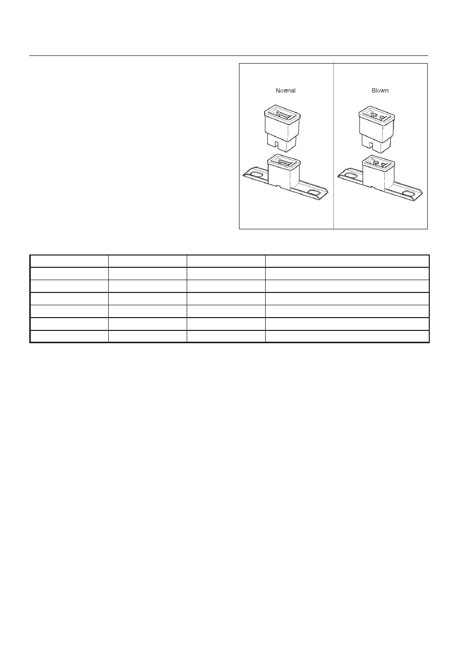
Fusible Link
The fusible link is primarily used to protect circuits where
high amounts of current flow and where it would not be
practical to use a fuse. For example, the starter circuit.
When a current overload occurs, the fusible link melts
open and interrupts the flow of current so as to prevent the
rest of the wiring harness from burning.
Determine the cause of the overload before replacing the
fusible link. the replacement fusible link must have the
same amperage specification as the original fusible link.
Never replace a blown fusible link with fusible link of a
different amperage specification. Doing so can result in
an electrical fire or other serious circuit damage.
A blown fusible link is easily identified as shown in the
figure.
D08RW154
Fusible Link Specifications
Type
Rating
Case Color
Maximum Circuit Current (A)
Connector
30A
Pink
15
Connector
40A
Green
20
Bolted
50A
Red
25
Bolted/Connector
60A
Yellow
30
Bolted
80A
Black
40
Bolted
100A
Blue
50