Opel Frontera UE. Manual - part 445
MANUAL TRANSMISSION
7B–53
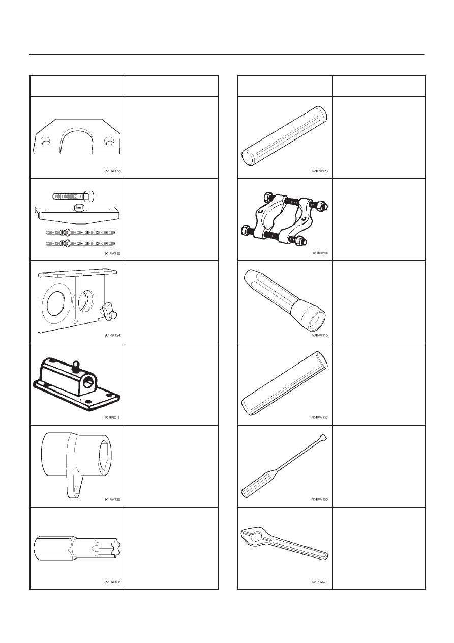
Special Tools (MUA)
ILLUSTRATION
TOOL NO.
TOOL NAME
5–8840–2158–0
Mainshaft collar remover
5–8840–2027–0
Puller
5–8840–2160–0
Holding fixture
5–8840–0003–0
Holding fixture base
5–8840–2156–0
Wrench
5–8840–0047–0
Tork bit wrench
(T–45)
ILLUSTRATION
TOOL NO.
TOOL NAME
5–8840–2159–0
Mainshaft end bearing
installer
5–8840–0015–0
Bearing
remover/installer
5–8840–0026–0
Front cover oil seal
installer
9–8522–1165–0
Mainshaft collar installer
5–8840–2291–0
Remover; Clutch release
bearing
5–8840–0133–0
Flange holder