Opel Frontera UE. Manual - part 304
6E2–22
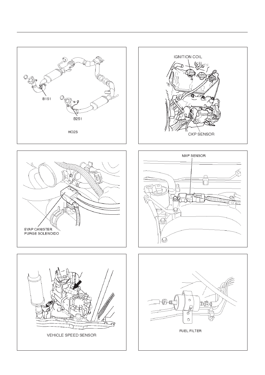
6VD1 3.2L ENGINE DRIVEABILITY AND EMISSIONS
Sensors and Miscellaneous Component Locators
150RX023
014RW141
T321067
T321070
055RW003
041RW013
|
|
|
6E2–22 6VD1 3.2L ENGINE DRIVEABILITY AND EMISSIONS Sensors and Miscellaneous Component Locators 150RX023 014RW141 T321067 T321070 055RW003 041RW013 |