Opel Frontera UE. Manual - part 303


  Index      Opel     Opel Frontera UE - service repair manual 1999-2001 year


Search            


Content   ..  301  302  303  304   ..


Opel Frontera UE. Manual - part 303


6E2–18

6VD1 3.2L ENGINE DRIVEABILITY AND EMISSIONS

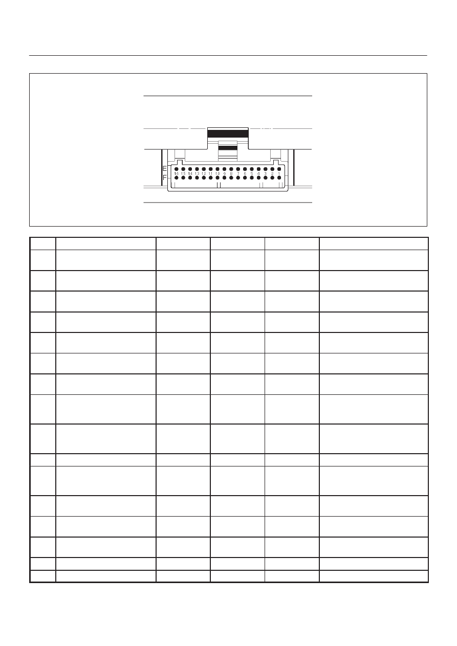
PCM Pinout Table, 32-Way Blue Connector – Row “E”

TS23346

PIN

PIN Function

Wire Color

IGN ON

ENG RUN

Refer To

E1

Vehicle Speed Sensor
Signal

YEL

0.0 V

0.1 V

Automatic Transmission
(4L30E)

E2

Vehicle Speed Sensor
Low

BRN

0.0 V

0.0 V

Automatic Transmission
(4L30E)

E3

Pressure Control Solenoid
Low

RED/GRN

0.0 V

0.0 V

Automatic Transmission
(4L30E)

E4

Pressure Control Solenoid
High

RED/BLK

0.0 V

0.0 V

Automatic Transmission
(4L30E)

E5

Exhaust Gas Recirculation
(EGR) Ignition

BLK/YEL

B+

B+

General Description and
Operation, EGR Control

E6

Exhaust Gas Recirculation
(EGR) Solenoid

YEL

B+

B+

General Description and
Operation, EGR Control

E7

Transmission Range
Signal “B”

PNK

0.0 V

0.0 V

Automatic Transmission
(4L30E)

E8

Throttle Position (TP)
Sensor

BLU

0.6 V

0.6 V

 (at idle)

General Description and
Operation, Throttle Position
Sensor

E9

Engine Coolant
Temperature (ECT)
Sensor

BLU/RED

2.3 V

2.1 V

General Description and
Operation, Engine Coolant
Temperature (ECT) Sensor

E10

Not Used

E11

Crankshaft Position (CKP)
Sensor +5 Volt Reference

BRN

5.0 V 

5.0 V

General Description and
Operation, Crankshaft
Position Sensor

E12

Transmission Range
Signal “A”

PNK/BLU

B+

B+

Automatic Transmission
(4L30E)

E13

Fuel Pump (FP) Relay

PNK/WHT

0.0 V

B+

On-Vehicle Service, Fuel
Pump Relay

E14

Shift High (BAND APPLY)

BRN/WHT

B+

B+

Automatic Transmission
(4L30E)

E15

A/C Request

GRN/BLK

0.0 V

0.0 V

Electric Cooling Fans

E16

Ignition Feed (1 of 2 F16)

RED/BLU

B+

B+

6E2–19

6VD1 3.2L ENGINE DRIVEABILITY AND EMISSIONS

PCM Pinout Table, 32-Way Blue Connector – Row “F”

TS23346

PIN

PIN Function

Wire Color

IGN ON

ENG RUN

Refer To

F1

Not Used

F2

Transmission Range
Signal “C”

BLU/WHT

0.0 V

0.0 V

Automatic Transmission
(4L30E)

F3

Transmission Range
Signal “P”

PNK/BLK

B+

B+

Automatic transmission
(4L30E)

F4

Brake Switch

RED

0.0 V

0.0 V

Automatic transmission
(4L30E)

F5

Power Switch

VIO

B+

B+

Automatic Transmission
(4L30E)

F6

Winter Switch

VIO

B+

B+

Automatic Transmission
(4L30E)

F7

Transmission Fluid
Temperature

GRN/RED

2.2 V

1.1 V

Automatic Transmission
(4L30E)

F8

Manifold Absolute
Pressure (MAP)

GRY

4.7 V

1.1 V

General Description and
Operation, Manifold Absolute
Pressure

F9

Rear Defogger Switch

YEL/GRN

B+

B+

Chassis Electrical

F10

Cruise Control

GRY/BLU

B+

B+

Automatic transmission
(4L30E)

F11

Kickdown Switch

LT BLU

B+

B+

Automatic Transmission
(4L30E)

F12

Diag

ORN/BLU

B+

B+

F13

Injector Cylinder #3

GRN

B+

B+

General Description and
Operation, Fuel Injector

F14

Shift “A” Solenoid

YEL/GRN

B+

B+

Automatic Transmission
(4L30E)

F15

Injector Cylinder #5

GRN/BLK

B+

B+

General Description and
Operation, Fuel Injector

F16

Ignition Feed (1 of 2 E16)

RED/BLU

B+

B+

6E2–20

6VD1 3.2L ENGINE DRIVEABILITY AND EMISSIONS

Component Locators

Engine Component Locator

515RW017

Engine Component Locator Table

Number

Name

Location

1

Crank Position (CKP) Sensor

Lower right side of the cylinder block

2

Linear Exhaust Gas Recirculation (EGR) Valve

Rear right of the engine

3

Knock Sensor

Right hand side between right bank and left bank
of the cylinder block

4

Manifold Absolute Pressure (MAP) Sensor

Bolted to the top the upper intake manifold

5

Common Chamber

Top of the engine

6

EVAP Canister Purge Valve

Bolted to the front of the coolant pipe

7

Fuel Pressure Regulator

Rear right side of the engine

8

Injection Coil 

Top of the cylinder engine

9

Air Cleaner

Left front of the engine bay

10

Mass Air Flow (MAF) Sensor

Attached to the air filter box

11

Camshaft Position (CMP) Sensor

On the rear side of the left cylinder head cover

12

Intake Air Temperature (IAT) Sensor

On the intake air dukt near the throttle body

13

Throttle Position (TP) Sensor

On the right of the  throttle body

14

Engine Coolant Temperature (ECT) Sensor

On the coolant crossover pipe at the front of the
engine,near the throttle body

15

Idle Air Control (IAC) Valve

On the left of the throttle body

16

Positive Crankcase Ventilator (PCV) Valve

On the left of the cylinder head

17

Fuse/Relay Box

Along the inside of the right fender

6E2–21

6VD1 3.2L ENGINE DRIVEABILITY AND EMISSIONS

Undercarriage Component Locator

014RW188

Undercarriage Component Locator Table

Number

Name

Location

1

Heated Oxygen Sensor (Bank 2)

Threated into the exhaust pipe ahead the
left–hand catalytic convertor

2

Fuel Filter

Located along the inside of the right frame
rail,ahead of the propeller shaft

3

Fuel Gauge Unit

Installed in the top of the fuel tank

4

Evaporative (EVAP) Canister

On the top of the bracket that is located behind
of the cross member

5

Vehicle Speed Sensor (VSS)

Protrudes from the transmission housing, just
ahead of the fuel tank

6

Heated Oxygen Sensor (Bank 1)

Threated into the exhaust pipe ahead
theright–hand catalytic convertor


Content   ..  301  302  303  304   ..