Opel Frontera UE. Manual - part 288


  Index      Opel     Opel Frontera UE - service repair manual 1999-2001 year


Search            


Content   ..  286  287  288  289   ..


Opel Frontera UE. Manual - part 288


6C–7

ENGINE FUEL (6VD1 3.2L)

Fuel Tube / Quick – Connector Fittings

Precautions

D

Lighting of Fires Prohibited.

D

Keep flames away from your work area to prevent the
inflammable from catching fire.

D

Disconnect the battery negative cable to prevent
shorting during work.

D

When welding or conducting other heat-generating
work on other parts, be sure to provide pretreatment
to protect the piping system from thermal damage or
spattering.

Cautions During Work

Do not expose the assembly to battery electrolyte or do
not wipe the assembly with a cloth used to wipe off spilt
battery electorolyte.
The piping wet with battery electrolyte cannot be used.
Be careful not to give a bending or twisting force to the
piping during the work. If deformed, replace with a new
piping.

Removal

1. Open the fuel cap to relieve the fuel pressure in the

tank.
If the fuel quick-connect fittings are dusty, clean with
an air blower, etc. and then remove it.

141RW036

As some pressure may remain in the piping, cover the
connector with a cloth, etc. to prevent the splashing
of fuel in the first disconnection of the piping.

2. For removal of the delivery pipe (feeding fuel to the

engine), hold the connector in one hand, and hold the
retainer tab with the other hand and pull out the
connector, as illustrated. The pipe can be removed
with the retainer attached.

141RW019

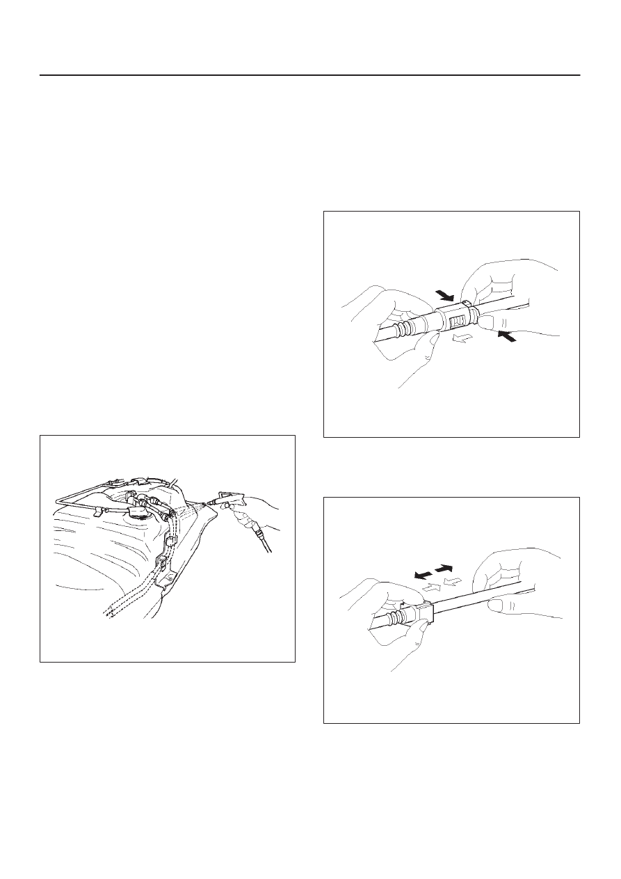
3. For removal of the return pipe (returnig fuel to the

tank), hold the pipe in one hand, and pull out the
connentor with the other hand while pressing the
square relieve button of the retainer, as illustrated.

141RW020

6C–8

ENGINE FUEL (6VD1 3.2L)

NOTE: This work should be done by hands. Do not use
any tools. Should the pipe can hardly be removed from
the connector, use a lubricant (light oil) and/or push and
pull the connector longitudinally until the pipe is removed.

141RW021

When reusing the delivery pipe retainer, reuse
without removing the retainer from the pipe. If the
retainer is damaged or deformed, however, replace
with a new retainer.
Cover the connectors removed with a plastic bag, etc.
to prevent the entry of dust or rain water.

141RW022

Reuse of Quick–Connector

(Delivery Pipe)

D

Replace the pipe and connector if scratch, dent or
crack is found.

D

Remove mud and dust from the pipe and make sure
that the end including spool is free of defects, such as
scratch, rust, and dent, which may cause poor
sealability. If defective, replace with a new pipe.

D

If the retainer removed according to the removal step
above is attached to the pipe, clean and insert it
straight into the quick-connector till it clicks. After it
clicks, try pulling it out to make sure that it is not drawn
and is securely locked.

NOTE: The retainer, once removed from the pipe, cannot
be reused. Just replace with a new retainer. Insert the
new retainer into the connector side until it clicks, and
connect the pipe as inserting it into the retainer until it
clicks.

141RW018

(Return Pipe)

D

Replace the pipe and connector if scratch, dent or
crack is found.

D

Remove mud or dust from the pipe and make sure
that the end including spool is free from defects, such
as scratch, rust, and dent, which may cause poor
sealability. If defective, replace with a new pipe.

6C–9

ENGINE FUEL (6VD1 3.2L)

D

After cleaning the pipe, insert it straight into the
connector until it clicks. After it clicks, try pulling it out
to make sure that it is not drawn and is securely
locked.

141RW017

Assembling Advice

Application of engine oil or light oil to the pipe facilitates
connecting work. The work should be started immediately
after lubrication, since dust may stick to the pipe surface
to cause poor sealability if a long time passes after
lubrication.
Test/Inspection After Assembling

1. Reconnect the battery negative cable.
2. Turn the ignition key to the “ON” position and check

pump startup sound. As the pump is actuated to raise
fuel pressure, check and see fuel leak from the piping
system.

3. Make sure of no fuel leakage by conducting the above

fuel leak check a few times.

4. Start the engine and make sure of stable idling speed

and normal vehicle run.The entry of dust during the
work may sometimes affect the fuel injection system.

Fuel Pump Relay

General Description

In order to control the FPAS operation, the FPAS relay is
provided. When the starter switch is turned to “ON”
position, the FPAS relay operates the FPAS for 2
seconds.
When it is turned to “START” position, the Engine Control
Module receives the reference pulse from the Ignition
Control Module and it operates the relay, again causing
the FPAS to feed fuel.

6C–10

ENGINE FUEL (6VD1 3.2L)

Fuel Tank

Fuel Tank and Associated Parts

140RX005

Legend

(1) Roll Over&Float Valve
(2) Retaining Cover
(3) Hose; Evaporative Fuel
(4) Hose; Air Breather
(5) Hose; Fuel Filler
(6) Bolt; Fuel Tank Protector Fixing
(7) Snap Ring
(8) Connector; Fuel Level Sensor
(9) Connector; Fuel Feed Pump

(10) Fuel Pump and Sender Assembly

(11) Fuel Feed Port

(12) Fuel Tube/Quick Connector
(13) Fuel Return Port
(14) Bolt; Fuel Tank Asm. Fixing
(15) Protector; Fuel Tank
(16) Fuel Tank Assembly
(17) Hose; Fuel Feed
(18) Hose; Fuel Return
(19) Protector; Heat

Removal

CAUTION: When repair to the fuel system has been
completed, start engine and check the fuel system
for loose connection or leakage. For the fuel system
diagnosis, see Section “Driveability and Emission”.

1. Disconnect battery ground cable.
2. Loosen fuel filler cap.
3. Support underneath of the fuel tank protector (15)

with a lifter.

4. Disconnect evaporative fuel hose (3) at the canister.
5. Disconnect fuel feed hose (17) and fuel return hose

(18) near the fuel filter.

NOTE: Plug both ends of the fuel hoses to prevent fuel
leakage.

6. Disconnect air breather hose (4) and fuel filler hose

(5) at the fuel filler neck.

NOTE: Cover fuel hose to prevent any dust entering.

7. Remove the four fuel tank assembly fixing bolts (14)

at four corners of the tank.

8. Let down the tank and disconnect the wiring

connectors (8,9).

9. Remove fuel tank assembly along with protectors

(15,19) .

10. Remove retaining cover (2) and roll over & float valve

(1) along with the evaporative fuel hose and pipe (3).


Content   ..  286  287  288  289   ..