Opel Frontera UE. Manual - part 286


  Index      Opel     Opel Frontera UE - service repair manual 1999-2001 year


Search            


Content   ..  284  285  286  287   ..


Opel Frontera UE. Manual - part 286


ENGINE COOLING 6B–13

Main Data and Specifications

General Specifications

M/T

A/T

Cooling system

Engine coolant forced circulation

Radiator

Tube type corrugated (2 tube in row)

Heat radiation capacity

70,000 kcal/h

77,800 kcal/h

Heat radiation area

9.74m

@

 (104.8ft

@

)

11.74m

@

 (126.4ft

@

)

Radiator front area

0.263m

@

 (2.83ft

@

)

Radiator dry weight

42N (9.4lb)

45N (10.1lb)

Radiator cap valve opening pressure

93.3 

 122.7kpa (13.5 

 17.8psi)

Engine coolant capacity

2.5lit (2.6U.S q.t.)

2.4lit (2.5U.S q.t.)

Engine coolant pump

Centrifugal impeller type

Delivery

300 (317) or more

Pump speed

5000 

±

 50 rpm

Thermostat

Wax pellet type with air hole

Valve opening temperature

74.5 

 78.5

°

C (166.1 

 173.3

°

F)

Engine coolant total capacity

11.1lit (2.93U.S qt)

10.0lit (2.64U.S qt)

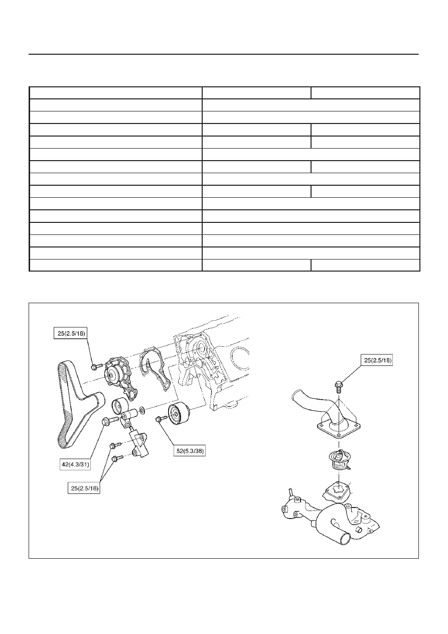
Torque Specifications

N·m (Kg·m/lb ft)

E06RW041

6B–14

ENGINE COOLING

Special Tool

ILLUSTRATION

TOOL NO.

TOOL NAME

5–8840–0277–0

(J–24460–01)

Tester; radiator cap

5–8840–2603–0

(J–33984–A)

Adapter; radiator cap

6C–1

ENGINE FUEL (6VD1 3.2L)

FRONTERA

ENGINE

ENGINE FUEL

CONTENTS

Service Precaution

6C–1

. . . . . . . . . . . . . . . . . . . . . . 

General Description

6C–2

. . . . . . . . . . . . . . . . . . . . . 

Fuel Metering

6C–3

. . . . . . . . . . . . . . . . . . . . . . . . . . . 

Fuel Filter

6C–4

. . . . . . . . . . . . . . . . . . . . . . . . . . . . . . 

Removal

6C–4

. . . . . . . . . . . . . . . . . . . . . . . . . . . . . 

Inspection

6C–4

. . . . . . . . . . . . . . . . . . . . . . . . . . . . 

Installation

6C–4

. . . . . . . . . . . . . . . . . . . . . . . . . . . . 

Inspection

6C–4

. . . . . . . . . . . . . . . . . . . . . . . . . . . . 

In–Tank Fuel Filter

6C–4

. . . . . . . . . . . . . . . . . . . . . 

Fuel Pump Flow Test

6C–5

. . . . . . . . . . . . . . . . . . . 

Fuel Pump

6C–6

. . . . . . . . . . . . . . . . . . . . . . . . . . . . . 

Fuel Pump and Associated Parts

6C–6

. . . . . . . . 

Removal

6C–6

. . . . . . . . . . . . . . . . . . . . . . . . . . . . . 

Installation

6C–6

. . . . . . . . . . . . . . . . . . . . . . . . . . . . 

Fuel Tube / Quick – Connector Fittings

6C–7

. . . . . 

Precautions

6C–7

. . . . . . . . . . . . . . . . . . . . . . . . . . . 

Cautions During Work

6C–7

. . . . . . . . . . . . . . . . . . 

Removal

6C–7

. . . . . . . . . . . . . . . . . . . . . . . . . . . . . 

Reuse of Quick–Connector

6C–8

. . . . . . . . . . . . . . . 

Assembling Advice

6C–9

. . . . . . . . . . . . . . . . . . . . . . 

Fuel Pump Relay

6C–9

. . . . . . . . . . . . . . . . . . . . . . . . 

General Description

6C–9

. . . . . . . . . . . . . . . . . . . . . 

Fuel Tank

6C–10

. . . . . . . . . . . . . . . . . . . . . . . . . . . . . . 

Fuel Tank and Associated Parts

6C–10

. . . . . . . . . 

Removal

6C–10

. . . . . . . . . . . . . . . . . . . . . . . . . . . . . 

Installation

6C–11

. . . . . . . . . . . . . . . . . . . . . . . . . . . . 

Fuel Gauge Unit

6C–11

. . . . . . . . . . . . . . . . . . . . . . . . 

Removal and Installation

6C–11

. . . . . . . . . . . . . . . . . 

Fuel Filler Cap

6C–11

. . . . . . . . . . . . . . . . . . . . . . . . . . 

General Description

6C–11

. . . . . . . . . . . . . . . . . . . . . 

Inspection

6C–11

. . . . . . . . . . . . . . . . . . . . . . . . . . . . 

Main Data and Specifications

6C–12

. . . . . . . . . . . . . 

Service Precaution

WARNING: THIS VEHICLE HAS A SUPPLEMENTAL
RESTRAINT SYSTEM (SRS).  REFER TO THE SRS
COMPONENT AND WIRING LOCATION VIEW IN
ORDER TO DETERMINE WHETHER YOU ARE
PERFORMING SERVICE ON OR NEAR THE SRS
COMPONENTS OR THE SRS WIRING. WHEN YOU
ARE PERFORMING SERVICE ON OR NEAR THE SRS
COMPONENTS OR THE SRS WIRING, REFER TO
THE SRS SERVICE INFORMATION. FAILURE TO
FOLLOW WARNINGS COULD RESULT IN POSSIBLE
AIR BAG DEPLOYMENT, PERSONAL INJURY, OR
OTHERWISE UNNEEDED SRS SYSTEM REPAIRS.

CAUTION: Always use the correct fastener in the
proper location. When you replace a fastener, use
ONLY the exact part number for that application.
ISUZU will call out those fasteners that require a
replacement after removal. ISUZU will also call out
the fasteners that require thread lockers or thread
sealant. UNLESS OTHERWISE SPECIFIED, do not
use supplemental coatings (Paints, greases, or other
corrosion inhibitors) on threaded fasteners or
fastener joint interfaces. Generally, such coatings
adversely affect the fastener torque and the joint
clamping force, and may damage the fastener. When
you install fasteners, use the correct tightening
sequence and specifications. Following these
instructions can help you avoid damage to parts and
systems.

SECTION

6C–2

ENGINE FUEL (6VD1 3.2L)

General Description

140RW066

Legend

(1) Fuel Filler Cap
(2) Fuel Tank
(3) Rollover Valve
(4) Fuel Pump and Sender Assembly
(5) Fuel Filter
(6) Fuel Rail Right
(7) Right Bank

(8) Fuel Rail Left
(9) Left Bank

(10) Fuel Pressure Control Valve

(11) Common Chamber

(12) Duty Solenoid Valve
(13) Throttle Valve
(14) Canister
(15) Evapo Pipe

When working on the fuel system, there are several
things to keep in mind:

D

Any time the fuel system is being worked on,
disconnect the negative battery cable except for
those tests where battery voltage is required.

D

Always keep a dry chemical (Class B) fire
extinguisher near the work area.

D

Replace all pipes with the same pipe and fittings that
were removed.

D

Clean and inspect “O” rings. Replace if required.

D

Always relieve the line pressure before servicing any
fuel system components.

D

Do not attempt repairs on the fuel system until you
have read the instructions and checked the pictures
relating to that repair.


Content   ..  284  285  286  287   ..