Opel Frontera UE. Manual - part 279


  Index      Opel     Opel Frontera UE - service repair manual 1999-2001 year


Search            


Content   ..  277  278  279  280   ..


Opel Frontera UE. Manual - part 279


6A–80

ENGINE MECHANICAL (6VD1 3.2L)

4. Reinstall the rod caps (12) to their original

positions.
Tighten the rod cap nuts.

Torque: 54 N·m (5.5 Kg·m/40 lb ft)

NOTE: Do not allow the crankshaft to rotate.

5. Remove the rod caps.

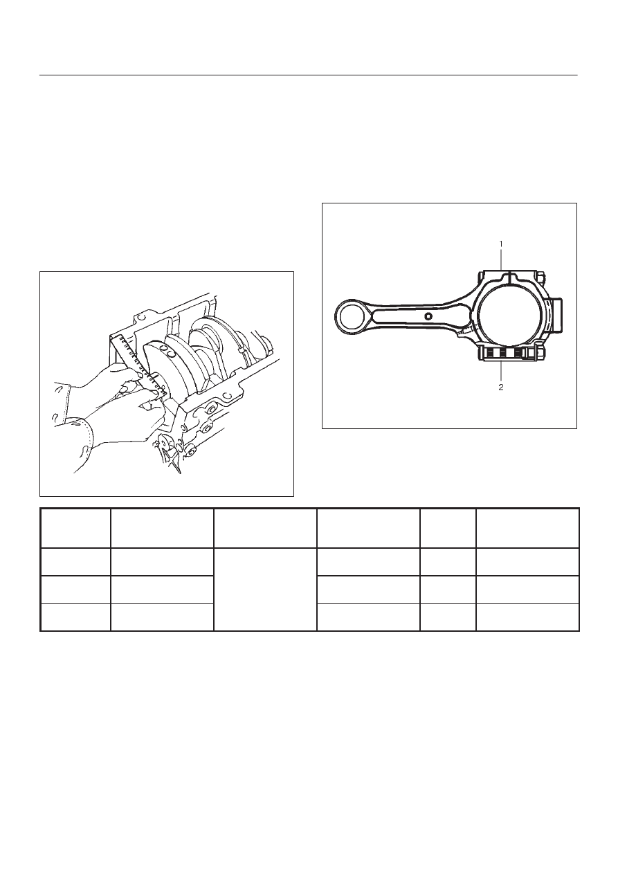
6. Measure the width of the plastigage and

determine the oil clearance. If the oil clearance
exceeds the limit, replace the rod bearing as a
set.

Standard : 0.019 mm–0.043 mm

(0.0007 in–0.0017 in)

Limit : 0.08 mm (0.003 in)

015RS008

7. Clean the plastigage from the bearings and the

crankshaft pins.

Con–rod Bearing Selection

Select and install the new connecting rod bearings,
paying close attention to the connecting rod big end
diameter size mark (1).

NOTE: Take care not to confuse the alignment mark (2)
and the size mark (1) during the installation procedure.

015RS034

1 Size Mark

Big end Bore 

Diameter

Crankshaft Pin

 Diameter

Connecting Rod

Bearing Thickness

(Reference)

Color of

Size

Mark

Oil Clearance 

(Reference)

A

56.994-57.000

(2.2439-2.2441)

1.512-1.516

(0.0595-0.0597)

Yellow

0.025-0.054

(0.0010-0.0021)

B

56.988-56.994

(2.2436-2.2439)

53.922-53.937

(2.1229-2.1235)

1.508-1.512

(0.0594-0.0595)

Green

0.027-0.056

(0.0011-0.0022)

C

56.982-56.988

(2.2434-2.2436)

1.504-1.508

(0.0592-0.0594)

Pink

0.029-0.058

(0.0011-0.0023)

Reassembly

1. Install connecting rod
2. Install piston

3. Install piston pin

D

Apply a thin coat of engine oil to the piston pin. Try to
insert the piston pin into the piston pin hole with
normal finger pressure.

NOTE: When  changing piston / connecting rod
combinations, do not change the piston / piston pin
combination and do not reuse the old piston pin.

6A–81

ENGINE MECHANICAL (6VD1 3.2L)

D

Attach the piston to the connecting rod with the
piston front mark and the connecting rod front mark
on the same side.

015RS036

D

With 5–8840–0551–0 Piston pin service set and a
press, press fit the piston pin.

NOTE: Heat the connecting rod small end to a suitable
temperature to ensure smooth installation.

015RX001

Legend

(1) Press Ram
(2) Piston
(3) Connecting Rod
(4) Piston Pin

4. Install piston ring with the piston ring expander.

The compression ring must be set with the T mark (1)
facing up.

Marked T : No.1 Compression ring

Marked T2 : No.2 Compression ring

015RS027

D

Install piston rings in the following sequence.

1. Oil ring

1. Expander ring
2. Upper side rail
3. Lower side rail

2. 2nd compression ring
3. 1st compression ring

D

The compression rings must be set with the T or T2
mark facing up.

Marked T : No.1 Compression ring

Marked T2 : No.2 Compression ring

D

After installation, apply engine oil to the entire
circumference of the piston rings. Check to see that
all the rings rotate smoothly.

015RS038

6A–82

ENGINE MECHANICAL (6VD1 3.2L)

5. Install piston and connecting rod assembly.

D

Insert the bearings into the connecting rods and
caps. Apply new engine oil to the bearing faces and
nuts.

D

Tighten the connecting rod cap nuts

Torque : 54 N·m (5.5 Kg·m/40 lb ft)

NOTE: Do not apply engine oil to the bearing back faces.

6. Oil gallery, refer to “Crankshaft and main bearing” in

this manual.

7. Oil strainer and O-ring.
8. Oil pipe and O-ring.
9. Install crankcase with oil pan, refer to “Oil pan and

Crankcase” in this manual.

10. Install cylinder head gasket.

11. Install Cylinder head assembly.

D

Refer to “Cylinder head” in this manual.

6A–83

ENGINE MECHANICAL (6VD1 3.2L)

Cylinder Block

Cylinder Block and Associated Parts

012RW010

Legend

(1) Cylinder Head Assembly
(2) Cylinder Head Gasket
(3) Crankcase with Oil Pan
(4) Oil Pipe and O-Ring
(5) Oil Strainer and O-Ring
(6) Oil Pump Assembly
(7) Cylinder Block Side Bolts

(8) Oil Gallery
(9) Piston and Connecting Rod Assembly

(10) Flywheel

(11) Rear Oil Seal Retainer Assembly

(12) Main Bearing Cap
(13) Crankshaft
(14) Cylinder Block

Disassembly

1. Remove cylinder head assembly.
2. Remove cylinder head gasket.
3. Remove crankcase with oil pan.
4. Remove oil pipe and O-ring.

5. Remove oil strainer and O-ring.
6. Remove oil pump assembly.
7. Remove crankcase side bolts.
8. Remove oil gallery.
9. Remove piston and connecting rod assembly.

10. Remove flywheel.


Content   ..  277  278  279  280   ..