Opel Frontera UE. Manual - part 243


  Index      Opel     Opel Frontera UE - service repair manual 1999-2001 year


Search            


Content   ..  241  242  243  244   ..


Opel Frontera UE. Manual - part 243


6E1–270

X22SE 2.2L ENGINE DRIVEABILITY AND EMISSION

Engine Control Module (ECM)

Electrostatic Discharge (ESD) 
Damage

Electronic components used in the control system are
often designed to carry very low voltage. Electronic
components are susceptible to damage caused by
electrostatic discharge. Less than 100 volts of static
electricity can cause damage to same electronic
components. By comparison, it takes as much as 4000
volts for a person to even feel the zap of a static
discharge. There are several way for a person to become
statically charged. The most common methods of
charging are by friction and by induction. An example of
charging by friction is a person sliding across a car seat.
Charging by induction occurs when a person with well
insulated shoes stands near a highly charged object and
momentarily touches ground. Charge of the same polarity
are drained off leaving the person highly charged with
opposite  polarity. Static charge can cause damage,
therefore, it is important to use care when handling and
testing electronic components.

NOTE: To prevent possible Electrostatic Discharge
damage, follow these guidelines:

D

Do not touch the control module connector pins or
soldered components on the control module circuit
board.

D

Do not open the replacement part package until the
part is ready to be installed.

D

Before removing the parts from the package, ground
the package to a known good ground on the vehicle.

D

If the parts been handled while sliding across the
seat, or while sitting from standing position, or walking
a distance, touch a known good ground before
installing the parts.

014RX002

NOTE: To prevent internal ECM damage, the ignition
must be OFF position in order to disconnect or reconnect
power to the ECM (for example: battery cable. pig tail,
ECM fuse, jumper cable, etc.).

IMPORTANT:

When replacing the production ECM

with a service ECM, it is important to transfer the
broadcast code and production ECM number to the
service ECM label. This will allow positive identification of
ECM parts throughout the service life of the vehicle.  Do
not record this information on ECM metal cover.
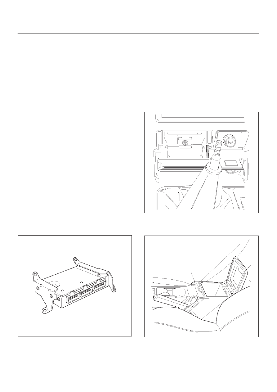
Removal Procedure

1. Disconnect the negative battery cable.
2. Block the wheels.
3. Remove ashtray inner.
4. Remove a screw located behind ashtray.

014RX014

5. Pull out Face trim of console.
6. Remove two screws located inside of center console

storage box and pull up rear part of center console.

014RX015

7. Unscrew the shift knob.
8. Remove four screw holding front part of the console

and pull the console up.

6E1–271

X22SE 2.2L ENGINE DRIVEABILITY AND EMISSION

9. Disconnect the red, white and blue electrical

connector at the ECM.

014RX016

10. Remove two nuts in the front of ECM.

11. Remove two nuts in the rear of ECM.

12. Pull the ECM out from dashboard.

014RX002

Installation Procedure

1. Place ECM into its position and secure by four

mounting screws.

014RX002

2. Connect all three connectors to ECM. All connectors

are color keyed. Same color male and female
connectors join together.

014RX017

6E1–272

X22SE 2.2L ENGINE DRIVEABILITY AND EMISSION

3. Install the front center console and secure by four

retaining screws.

014RX016

4. Install the rear center console and secure it by two

retaining screw into storage box.

014RX015

5. Snap face plate into its position and secure it by a

screw.

6. Insert ashtray inner.
7. Insert the shift knob.
8. Connect the negative battery cable.

9. Remove wheel blocks.

014RX014

Throttle Position (TP) Sensor

Removal Procedure

1. Disconnect the negative battery cable.
2. Disconnect the TPS electrical connector.
3. Remove the two screws and TP sensor from the

throttle body.

NOTE: Do not clean the TP sensor by soaking it in
solvent. The sensor will be damaged as a result.

101RX002

6E1–273

X22SE 2.2L ENGINE DRIVEABILITY AND EMISSION

Function Check

Use a Tech 2 to check the TP sensor output voltage at
closed throttle.

D

The voltage should be under 0.25 volts.

D

If the reading is greater than 0.25 volts, check the
throttle shaft to see if it is binding. Check that the
throttle cable is properly adjusted, also. Refer to
Throttle Cable Adjustment. 

D

If the throttle shaft is not binding and the throttle cable
is properly adjusted, install a new TP sensor.

101RX003

Installation Procedure

1. Install the TP sensor on the throttle body with two

screws.

101RX003

2. Connect the electrical connector.

3. Connect the negative battery cable.

101RX002

Vehicle Speed Sensor (VSS)

Removal Procedure

1. Disconnect the negative battery cable.
2. VSS is located on the right side of the transmission

case just ahead of the rear propeller shaft.
Disconnect the VSS electrical connector.

3. Remove the bolt and the VSS from the transmission

case by wiggling it slightly and pulling it straight out.

IMPORTANT:

Have a container ready to catch any fluid

that leaks out when the VSS is removed from the transfer
case.

014RX020


Content   ..  241  242  243  244   ..