Opel Frontera UE. Manual - part 187


  Index      Opel     Opel Frontera UE - service repair manual 1999-2001 year


Search            


Content   ..  185  186  187  188   ..


Opel Frontera UE. Manual - part 187


6E1–46

X22SE 2.2L ENGINE DRIVEABILITY AND EMISSION

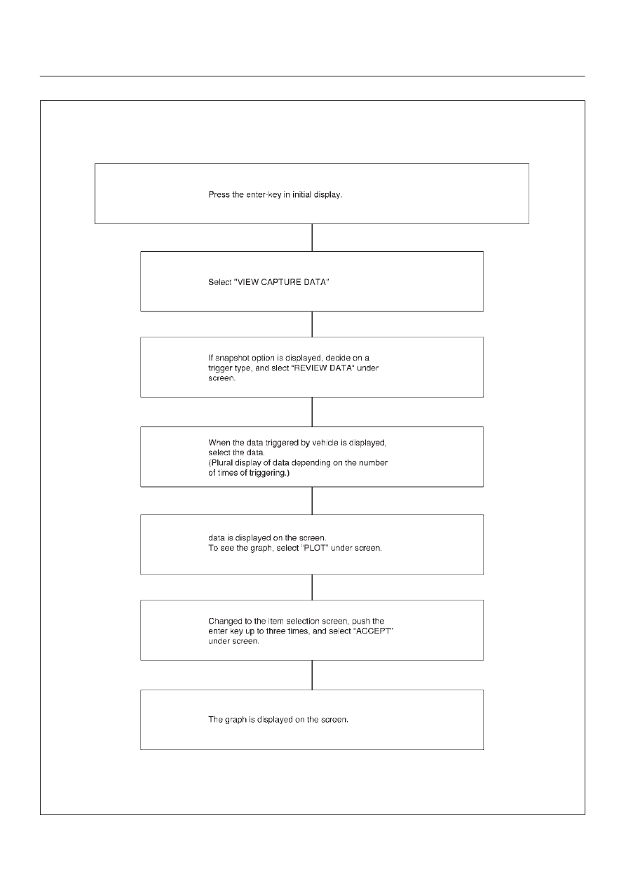
Flow Chart for Snapshot Replay (Plotting Graph)

060RX040

6E1–47

X22SE 2.2L ENGINE DRIVEABILITY AND EMISSION

PRIMARY SYSTEM–BASED

DIAGNOSTICS

Primary System–Based Diagnostics

There are primary system–based diagnostics which
evaluate system operation and its effect on vehicle
emissions. The primary system–based diagnostics are
listed below with a brief description of the diagnostic
function:

Oxygen Sensor Diagnosis
The fuel control heated oxygen sensor (HO2S 1) is
diagnosed for the following conditions:

D

Heater performance (time to activity on cold start)

D

Slow response

D

Response time (time to switch R/L or L/R)

D

Inactive signal (output steady at bias voltage –
approx. 450 mV)

D

Signal fixed high

D

Signal fixed low

The catalyst monitor heated oxygen sensor (HO2S 2) is
diagnosed for the following conditions:

D

Heater performance (time to activity on cold start).

D

Signal fixed low during steady state conditions or
power enrichment (hard acceleration when a rich
mixture should be indicated).

D

Signal fixed high during steady state conditions or
deceleration mode (deceleration when a lean mixture
should be indicated).

D

Inactive sensor (output steady at approx. 438 mV).

If the oxygen sensor pigtail wiring, connector or terminal
are damaged, the entire oxygen sensor assembly must
be replaced. DO NOT attempt to repair the wiring,
connector or terminals. In order for the sensor to function
properly, it must have clean reference air provided to it.
This clean air reference is obtained by way of the oxygen
sensor wire(s). Any attempt to repair the wires, connector
or terminals could result in the obstruction of the
reference air and degrade oxygen sensor performance.
Refer to On–Vehicle Service, Heated Oxygen Sensors.

Fuel Control Heated Oxygen Sensors 

The main function of the fuel control heated oxygen
sensors is to provide the control module with exhaust
stream oxygen content information to allow proper fueling
and maintain emissions within mandated levels. After it
reaches operating temperature, the sensor will generate
a voltage, inversely proportional to the amount of oxygen
present in the exhaust gases. The control module uses
the signal voltage from the fuel control heated oxygen
sensors while in ”Closed Loop” to adjust fuel injector
pulse width. While in ”Closed Loop”, the ECM can adjust
fuel delivery to maintain an air/fuel ratio which allows the
best combination of emission control and driveability. The
fuel control heated oxygen sensors are also used to
determine catalyst efficiency.

HO2S Heater

Heated oxygen sensors are used to minimize the amount
of time required for ”Closed Loop” fuel control to begin
operation and to allow accurate catalyst monitoring. The
oxygen sensor heater greatly decreases the amount of
time required for fuel control sensor (HO2S 1) to become
active. Oxygen sensor heaters are required by the
catalyst monitor sensor (HO2S 2) to maintain a
sufficiently high temperature which allows accurate
exhaust oxygen content readings further away from the
engine.

6E1–48

X22SE 2.2L ENGINE DRIVEABILITY AND EMISSION

ON–BOARD DIAGNOSTIC (OBD) SYSTEM CHECK

D06RX108

Circuit Description

The on–board diagnostic system check is the starting
point for any driveability complaint diagnosis. Before
using this procedure, perform a careful visual/physical
check of the ECM and engine grounds for cleanliness and
tightness.
The on–board diagnostic system check is an organized
approach to identifying a problem created by an
electronic engine control system malfunction.

Diagnostic Aids

An intermittent may be caused by a poor connection,
rubbed–through wire insulation or a wire broken inside the
insulation. Check for poor connections or a damaged
harness. Inspect the ECM harness and connectors for
improper mating, broken locks, improperly formed or
damaged terminals, poor terminal–to–wire connection,
and damaged harness.

Test Description

Number(s) below refer to the step number(s) on the
Diagnostic Chart:
1. The MIL (”Check Engine” lamp) should be ON

steady with the ignition ON/engine OFF. If not,
isolate the malfunction in the MIL circuit.

2. Checks the Class 2 data circuit and ensures that the

ECM is able to transmit serial data.

3. This test ensures that the ECM is capable of

controlling the MIL and the MIL driver circuit is not
shorted to ground.

 4. If the engine will not start, the Cranks But Will Not

Run chart should be used to diagnose the condition.

 7. A Tech 2 parameter which is not within the typical

range may help to isolate the area which is causing
the problem.

6E1–49

X22SE 2.2L ENGINE DRIVEABILITY AND EMISSION

On–Board Diagnostic (OBD) System Check


Step

Action

Value(s)

Yes

No

1

1. Ignition ON, engine OFF.
2. Observe the malfunction indicator lamp (MIL or

”Check Engine lamp”).

Is the MIL (”Check Engine lamp”) ON?

Go to Step 2

Go to No MIL

2

1. Ignition OFF.
2. Install a Tech 2.
3. Ignition ON.
4. Attempt to display ECM engine data with the Tech 2.

Does the Tech 2 display ECM data?

Go to Step 3

Go to Step 8

3

1. Using the Tech 2 output tests function, select MIL

dash lamp control and command the MIL OFF.

2. Observe the MIL.

Did the MIL turn OFF?

Go to Step 4

Go to MIL

(”Check

Engine

Lamp”) On

Steady

4

Attempt to start the engine.

Did the engine start and continue to run?

Go to Step 5

Go to Cranks

But Will Not

Run

5

Select ”Display DTCs” with the Tech 2.

Are any DTCs stored?

Go to Step 6

Go to Step 7

6

Are two or more of the following DTCs stored? P0107,
P0113, P0118, P0122, P0123.

Go to

“Multiple

ECM

Information

Sensor DTCs

Set”

Go to

applicable
DTC table

7

Compare ECM data values displayed on the Tech 2 to
the typical engine scan data values.

Are the displayed values normal or close to the typical
values?

Go to “Typial

Scan” Data

Value

Go to

indicated

Component

System
Checks

8

1. Ignition OFF, disconnect the ECM.
2. Ignition ON, engine OFF.
3. Check the Class 2 data circuit for an open, short to

ground, or short to voltage. Also, check the DLC
ignition feed circuit for an open or short to ground
and the DLC ground circuits for an open.

4. If a problem found, repair as necessary.

Was a problem found?

Go to Step 2

Go to Step 9

9

1. Attempt to reprogram the ECM. Refer to Engine

Control Module (ECM) in On–Vehicle Service.

2. Attempt to display ECM data with the Tech 2.

Does the Tech 2 display ECM engine data?

Go to Step 2

Go to Step 10

10

Replace the ECM.

Is the action complete?

Verify repair


Content   ..  185  186  187  188   ..