Opel Frontera UE. Manual - part 1752


  Index      Opel     Opel Frontera UE - service repair manual 1999-2001 year


Search            


Content   ..  1750  1751  1752  1753   ..


Opel Frontera UE. Manual - part 1752


SUPPLEMENTAL RESTRAINT SYSTEM

9J–49

Passenger Air Bag Assembly

Service Precaution

WARNING:  SAFETY PRECAUTIONS MUST BE 
FOLLOWED WHEN HANDLING A DEPLOYED AIR 
BAG ASSEMBLY. AFTER DEPLOYMENT, THE AIR 
BAG ASSEMBLY SURFACE MAY CONTAIN A SMALL 
AMOUNT OF SODIUM HYDROXIDE, A BY-PRODUCT 
OF THE DEPLOYMENT REACTION, THAT IS 
IRRITATING TO THE SKIN AND EYES. MOST OF THE 
POWDER ON THE AIR BAG ASSEMBLY IS 
HARMLESS. AS A PRECAUTION, WEAR GLOVES 
AND SAFETY GLASSES WHEN HANDLING A 
DEPLOYED AIR BAG ASSEMBLY, AND WASH YOUR 
HANDS WITH MILD SOAP AND WATER 
AFTERWARDS.

WARNING:  WHEN CARRYING A LIVE AIR BAG 
ASSEMBLY, MAKE SURE THE BAG AND TRIM 
COVER ARE POINTED AWAY FROM YOU. NEVER 
CARRY AIR BAG ASSEMBLY BY THE WIRES OR 
CONNECTOR ON THE UNDERSIDE OF MODULE. IN 
THE CASE OF AN ACCIDENTAL DEPLOYMENT, THE 
BAG WILL THEN DEPLOY WITH MINIMAL CHANCE 
OF INJURY. WHEN PLACING A LIVE AIR BAG 
ASSEMBLY ON A BENCH OR OTHER SURFACE, 
ALWAYS FACE BAG AND TRIM COVER UP, AWAY 
FROM THE SURFACE. NEVER REST A STEERING 
COLUMN ASSEMBLY ON THE STEERING WHEEL 
WITH THE AIR BAG ASSEMBLY FACE DOWN AND 
COLUMN VERTICAL. THIS IS NECESSARY SO THAT 
A FREE SPACE IS PROVIDED TO ALLOW THE AIR 
BAG ASSEMBLY TO EXPAND IN THE UNLIKELY 
EVENT OF ACCIDENTAL DEPLOYMENT. 
OTHERWISE, PERSONAL INJURY COULD RESULT.

In the event deployment has occurred, inspect coil 
assembly wire for any signs of scorching, melting or any 
other damage due to excessive heat. If the coil has 
been damaged, replace it.
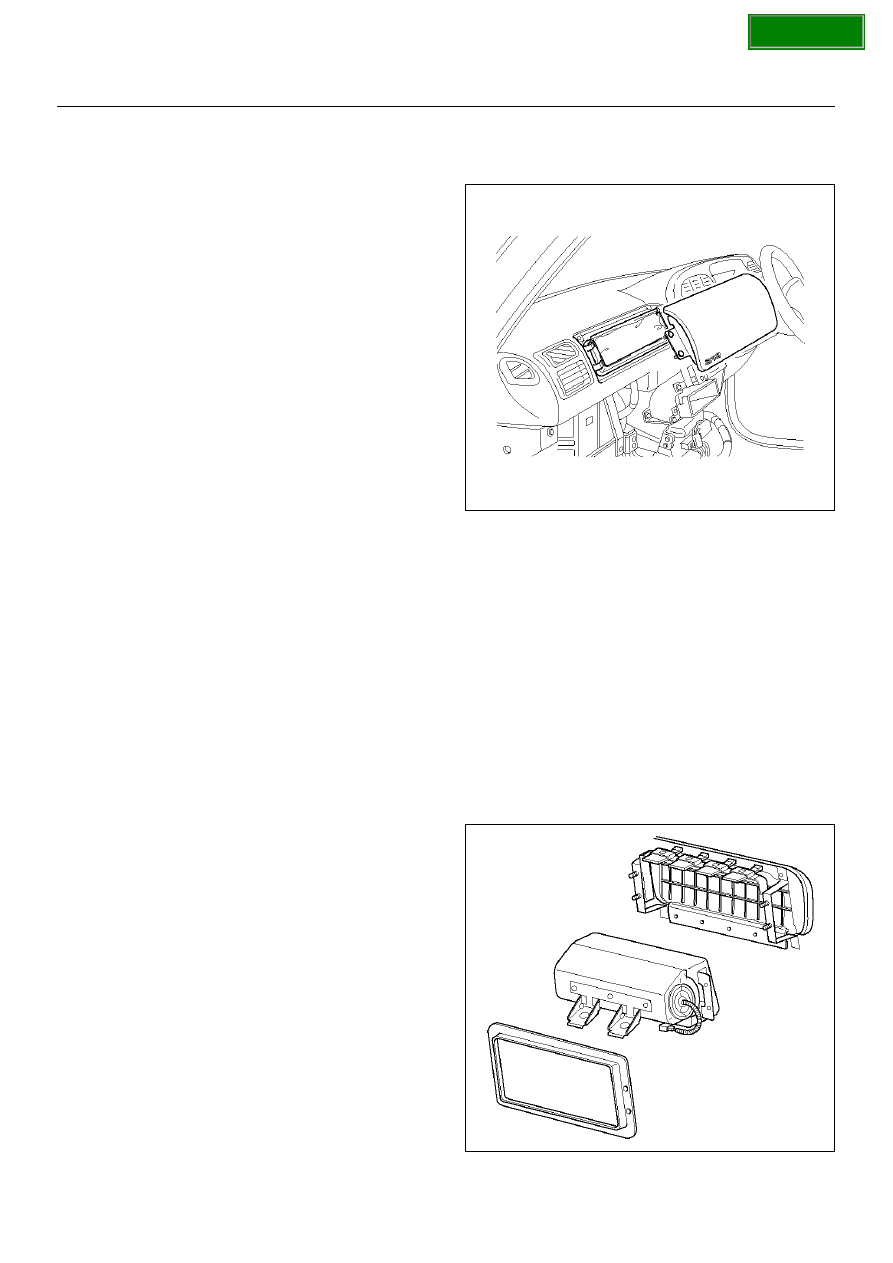
Removal

1. Disable the SRS. (Refer to “Disabling the SRS" in 

this section.)

2. Remove glove box assembly.

3. Disconnect passenger air bag assembly harness 

connector.

4. Remove air bag assembly fixing bolts and nuts.

5. Remove reinforcement.

6. Remove passenger air bag assembly from glove 

box opening of instrument panel.

827RX051

Installation

1. Install passenger air bag assembly from glove box 

opening of instrument panel.

2. Install reinforcement from glove box opening of 

instrument panel.

3. Install air bag assembly fixing nuts and bolts, and 

tighten to specified torque.

Torque: 7.8 N·m (69 lbin)

4. Connect air bag assembly harness connector.

5. Install glove box assembly.

6. Enable the SRS (Refer to “Enabling the SRS" in this 

section.)

827RW062

SECTION

9J–50

SUPPLEMENTAL RESTRAINT SYSTEM

Main Data and Specifications

Fastener Tightening Specification

Application

N·m

kg·m

Ib Ft

Ib In

SDM

10

1.0

87

Driver air bag fixing bolt

8.8

0.9

78

Steering wheel fixing bolt

34

3.5

25

Steering column (dash panel side fixing bolts)

20

2.0

15

Steering column (Cross beam side fixing nuts)

17

1.7

13

Steering column (Universal joint fixing bolt)

31

3.2

23

Passenger Air Bag fixing bolts and nuts

6

0.6

52

SECTION

SUPPLEMENTAL RESTRAINT SYSTEM

9J–51

SRS Air Bag System Inspection Standards For Repair

Inspection Standards
In cases of collision: When any type of collision has occurred regardless of air bag deployment.
In cases of trouble code: When trouble code has been detected by TECH 2 in case of the AIR BAG WARNING LIGHT 
failing to work or remaining lighted.

Parts Name

Inspection Standard

Part Replacement Standard

Collision

Trouble

Driver Air bag 
Assembly

1. Air bag has deployed due to collision.

2. Pad surface has crack or scratch.

3. Connector has cracks.

4. Harness is disconnected or scratched.

5. Air bag is soaked in water, oil etc.

6. Air bag has fallen from a height of about 10 cm (3.3) feet.

7. Trouble diagnosis in Workshop Manual resulted in part 

replacement.

Passenger Air bag 
Assembly

Sensing and 
Diagnostic Module 
(SDM)

1. Air bag has deployed due to collision.

2. SDM is crack or deformed.

3. Connector has cracks.

4. SDM has fallen from a height of about 100 cm (3.3 feet).

5. Trouble diagnosis in Workshop Manual resulted in part 

replacement.

SRS Coil Assembly

1. Burn or melt due to overheat.

2. Case is cracked or deformed.

3. Trouble diagnosis in Workshop Manual resulted in part 

replacement.

SRS Harness

1. Air bag circuit wire harness is disconnected or damaged.

2. Connector has cracks.

3. Trouble diagnosis in Workshop Manual resulted in part 

replacement.

Steering Wheel

1. Bracket is deformed.

2. A new air bag cannot be installed with ease.

3. When a new air bag is installed, pad interferes with the steering 

wheel, and clearance is uneven.

Steering Column

1. Capsule is broken.

2. The fitting of column collapses.

3. Bellows pipe is deformed.

Instrument Panel & 
Knee bolster & 
Cover Glove box. 
Seat Seat Belt 
Wood shield Glass

1. Dent, bend, cracks, and deform.

Mounts

1. Repair or replace if dent, bend, cracks, and deform are found.

2. Retighten to specified torque if loose.

SECTION

RESTRAINT CONTROL SYSTEM

9J1–1

RESTRAINTS

SRS CONTROL SYSTEM

CONTENTS

Service Precaution......................................... 9J1 - 1
Diagnostic Information ................................... 9J1 - 2
Parts For Electrical Circuit ............................. 9J1 - 4
System Schematic ......................................... 9J1 - 5
SRS Diagnostic System Check ..................... 9J1 - 5
Chart A  SDM Integrity Check........................ 9J1 - 9
Chart B “AIR BAG" Warning Lamp Comes

“ON" Steady ................................................. 9J1 - 11

Chart C  “AIR BAG" Warning Lamp Does 

Not Comes “ON" Steady .............................. 9J1 - 13

DTC 15  Passenger Deployment Loop

Resistance High........................................... 9J1 - 16

DTC 16  Passenger Deployment Loop 

Resistance Low............................................ 9J1 - 19

DTC 17  Passenger Deployment Loop 

Open ............................................................ 9J1 - 22

DTC 18  Passenger Deployment Loop 

Short To Ground .......................................... 9J1 - 25

DTC 19  Passenger Deployment Loop 

Short To Voltage .......................................... 9J1 - 28

DTC 21  Driver Deployment Loop

Resistance High........................................... 9J1 - 31

DTC 22  Driver Deployment Loop 

Resistance Low............................................ 9J1 - 34

DTC 24  Driver Deployment Loop 

Short To Ground .......................................... 9J1 - 37

DTC 25  Driver Deployment Loop 

Short To Voltage .......................................... 9J1 - 40

DTC 26  Driver Deployment Loop Open ........ 9J1 - 44
DTC 51  Deployment Event Commanded ..... 9J1 - 47
DTC 53  Deployment Commanded With

Deployment Loop Fault Or Energy Reserves 
Out Of Range............................................... 9J1 - 49

DTC 61  Warning Lamp Circuit Failure.......... 9J1 - 52
DTC 71  Internal SDM Fault .......................... 9J1 - 54

Service Precaution

WARNING:  THIS VEHICLE HAS A SUPPLEMENTAL
RESTRAINT SYSTEM (SRS). REFER TO THE SRS
COMPONENT  AND WIRING LOCATION VIEW IN
ORDER TO DETERMINE WHETHER YOU ARE
PERFORMING SERVICE ON OR NEAR THE SRS
COMPONENTS OR THE SRS WIRING. WHEN YOU
ARE PERFORMING SERVICE ON OR NEAR THE
SRS COMPONENTS OR THE  SRS WIRING, REFER
TO THE SRS SERVICE INFORMATION. FAILURE TO
FOLLOW WARNINGS COULD RESULT IN POSSIBLE
AIR  BAG DEPLOYMENT, PERSONAL INJURY, OR
OTHERWISE UNNEEDED SRS SYSTEM REPAIRS.

CAUTION:  Always use the correct fastener in the
proper location. When you replace a fastener, use
ONLY the exact part number for that application.
ISUZU will call out those fasteners that require a
replacement after  removal. ISUZU will also call out
the fasteners that require thread lockers or thread
sealant. UNLESS OTHERWISE  SPECIFIED, do not
use supplemental coatings (Paints, greases, or
other corrosion inhibitors) on threaded fasteners  or
fastener joint interfaces. Generally, such coatings
adversely affect the fastener torque and the joint
clamping force,  and may damage the fastener.
When you install fasteners, use the correct
tightening sequence and specifications.  Following
these instructions can help you avoid damage to
parts and systems.

SECTION


Content   ..  1750  1751  1752  1753   ..