Content .. 1640 1641 1642 1643 ..
Opel Frontera UE. Manual - part 1642
ENTERTAINMENT
8C–5
Speaker
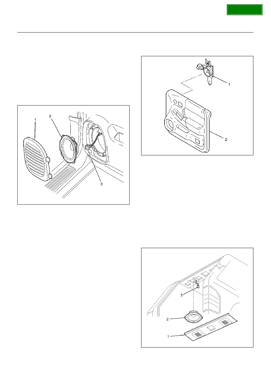
Front Speaker
Removal
1. Disconnect the battery ground cable.
2. Pull the grille (1) to release the locks and then
remove it.
3. Remove four screws and disconnect the connector
(3) to remove the speaker (2).
890RX012
Installation
To install, follow the removal steps in the reverse order.
Tweeter Assembly
Removal
1. Disconnect the battery ground cable.
2. Remove the front door trim pad (2).
• Refer to Front Window Regulator, Glass And
Glass Run in Body Structure section:
3. Remove the tweeter (1).
• Disconnect the connector.
635RW009
Installation
To install, follow the removal steps in the reverse order.
Rear Speaker
Removal
1. Disconnect the battery ground cable.
2. Remove the roof rear lining (1).
• Release the locks and clips.
3. Remove the speaker (2).
• Remove the four screws.
• Disconnect the connector (3).
890RX028