Opel Frontera UE. Manual - part 1553


  Index      Opel     Opel Frontera UE - service repair manual 1999-2001 year


Search            


Content   ..  1551  1552  1553  1554   ..


Opel Frontera UE. Manual - part 1553


6E–427

6VD1 3.2L ENGINE DRIVEABILITY AND EMISSIONS

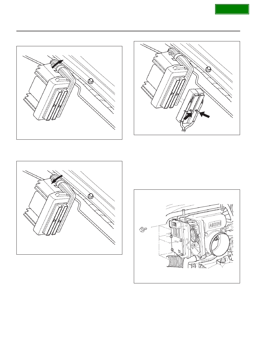
5. After removing the clip which fixes the PCM to the

bracket, remove PCM.

060RY00067

Installation Procedure

1. Install the PCM to bracket and fix with the clip.

060RY00066

2. Connect the PCM electrical connectors.

3. Install the two screws to PCM electrical connectors.

060RY00065

Throttle Position (TP) Sensor

Removal Procedure

1. Disconnect the negative battery cable.
2. Disconnect the TPS electrical connector.
3. Remove the bolts and the TP sensor from the throttle

body.

060RY00159

NOTE: Do not clean the TP sensor by soaking it in
solvent.  The sensor will be damaged as a result.

SECTION

6E–428

6VD1 3.2L ENGINE DRIVEABILITY AND EMISSIONS

Function Check

Use a Tech 2 to check the TP sensor output voltage at
closed throttle.

D

The voltage should be TP1 about 0.4V, TP2 about
4.6V and TP3 about 4.6V.

D

If the reading is abnormal value, check the throttle
shaft to see if it is binding.

Installation Procedure

1. Install the TP sensor on the throttle body with the

bolts.

060RY00159

2. Connect the TP electrical connector.
3. Install the negative battery cable.

Vehicle Speed Sensor (VSS)

Removal Procedure

CAUTION: The VSS is located on the right side of
the transfer case just ahead of the rear propeller
shaft and very close to the exhaust pipes for 4WD
and on the extension cover for 2WD.  Be sure that the
exhaust pipes are cool enough to touch before trying
to remove the VSS.  If the pipes are hot, you could be
burned.

1. Disconnect the negative battery cable.

2. Disconnect the VSS electrical connector.

TS23748

3. Remove the bolt and the clamp securing the VSS in

place.

IMPORTANT:

Have a container ready to catch any fluid

that leaks out when the VSS is removed from the transfer
case for 4WD and on the extension cover for 2WD.

TS23780

4. Remove the VSS from the transfer case by wiggling it

slightly and pulling it straight out.

SECTION

6E–429

6VD1 3.2L ENGINE DRIVEABILITY AND EMISSIONS

Inspection Procedure

1. Inspect the electrical connector for signs of corrosion

or warping.  Replace the VSS if the electrical
connector is corroded or warped.

2. Inspect the VSS driven gear for chips, breaks, or worn

condition.  Replace the VSS if the driven gear is
chipped, broken or worn.

3. Inspect the O-ring for wear, nicks, tears, or

looseness.  Replace the O-ring if necessary.

Installation Procedure

1. Install the VSS in the transfer case with the notch for

the connector facing the rear.

2. Secure the VSS in place with the clamp and the bolt.

Tighten

D

Tighten the bolt to 16 N·m (12 lb ft.).

TS23780

3. Connect the VSS electrical connector.

TS23748

4. Check the transfer case oil level.  Add fluid if

necessary.

5. Connect the negative battery cable.

Air Cleaner/Air Filter

Removal Procedure

1. Loosen the clamp between the air cleaner lid and the

mass air flow sensor.

025RY00001

2. Release the four latches securing the lid to the air

cleaner housing.

3. Remove the air cleaner lid.
4. Remove the air filter element.
5. Remove the retaining bolts and the air cleaner

housing from the vehicle.

025RY00002

Legend

(1) Air Cleaner Housing
(2) Air Filter Element
(3) Air Cleaner Lid

SECTION

6E–430

6VD1 3.2L ENGINE DRIVEABILITY AND EMISSIONS

Installation Procedure

1. Install the air cleaner housing in the vehicle with the

retaining bolts.

2. Install the air filter element in the air cleaner housing.
3. Install the air cleaner lid on the MAF sensor and the air

cleaner housing.

025RY00003

Legend

(1) Air Cleaner Housing
(2) Air Filter Element
(3) Air Cleaner Lid
(4) Mass Air Flow Sensor

4. Tighten the clamp and secure the four latches

between the lid and the air cleaner housing.

Common Chamber

Removal and Installation Procedure

Refer to Common Chamber in Engine Mechanical
section.

Accelerator Pedal Replacement

Removal Procedure

1. Disconnect the negative battery cable.

2. Disconnect the electrical harness from the

accelerator position sensor.

101RY00006

Legend

(1) Accelerator Position Sensor
(2) Accelerator Pedal Assembly

3. Remove the two screws from the accelerator pedal

assembly.

101RY00007

4. Remove the accelerator pedal assembly from the

bulkhead.

SECTION


Content   ..  1551  1552  1553  1554   ..