Opel Frontera UE. Manual - part 1552


  Index      Opel     Opel Frontera UE - service repair manual 1999-2001 year


Search            


Content   ..  1550  1551  1552  1553   ..


Opel Frontera UE. Manual - part 1552


6E–423

6VD1 3.2L ENGINE DRIVEABILITY AND EMISSIONS

Installation Procedure

1. Install the IAT sensor into the grommet in the intake

air duct.

2. Correct the IAT electrical connector.

TS23741

3. Install the engine cover.
4. Connect the negative battery cable.

ION Sensing Module

Removal Procedure

1. Disconnect the negative battery cable.
2. Disconnect the ION sensing module connector.
3. Remove the bolts and the ION sensing module from

the common chamber.

060R100143

Installation Procedure

1. Install the ION sensing module on the common

chamber with the bolts.

Tighten

D

Tighten the ION sensing module to 4 N·m (35 lb
in.).

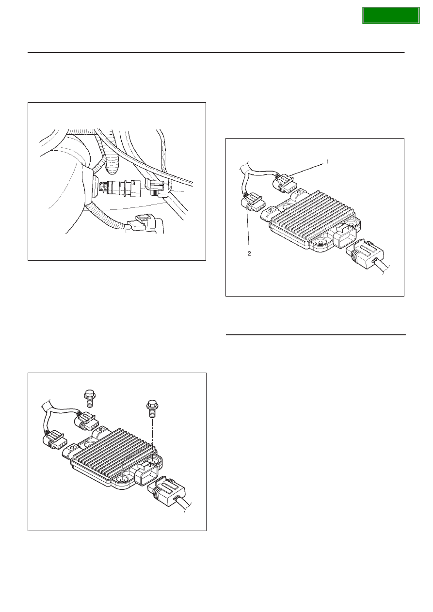
2. Connect the ION sensing module connectors as

shown in the illustration.

060RY00003

Legend

(1) Green (Light Blue) Color Connector
(2) Blue Color Connector

3. Connect the negative battery cable.

SECTION

6E–424

6VD1 3.2L ENGINE DRIVEABILITY AND EMISSIONS

Mass Air Flow (MAF) Sensor

Removal Procedure

1. Disconnect the negative battery cable.
2. Disconnect the electrical connector from the MAF

sensor.

TS23740

3. Loosen the clamps which secure the intake air duct

and the air cleaner to the MAF sensor.

4. Remove the intake air duct from the MAF sensor.
5. Remove the MAF sensor from the air cleaner.

TS23781

Installation Procedure

1. Install the MAF sensor on the air cleaner with the

clamp.

2. Install the intake air duct and the clamp on the MAF

sensor.

TS23781

3. Tighten the clamps to secure the MAF sensor to the

intake air duct and the air cleaner.

4. Connect the MAF electrical connector.
5. Connect the negative battery cable.

SECTION

6E–425

6VD1 3.2L ENGINE DRIVEABILITY AND EMISSIONS

Manifold Absolute Pressure

(MAP) Sensor

Removal Procedure

1. Disconnect the negative battery cable.
2. Disconnect the electrical connector from the MAP

sensor.

055RY00001

3. Remove the bolt securing the MAP sensor to the

mounting bracket on the common chamber.

4. Remove the MAP sensor from the mounting bracket.

055RW002

Installation Procedure

1. Install the MAP sensor in the mounting bracket.

055RW002

2. Install the mounting bracket retaining bolt on the

common chamber.

Tighten

D

Tighten the bolt to 20 N·m (12 lb ft.).

3. Connect the MAP electrical connector.

055RY00001

4. Connect the negative battery cable.

SECTION

6E–426

6VD1 3.2L ENGINE DRIVEABILITY AND EMISSIONS

Malfunction Indicator Lamp

(MIL)

Removal and Installation Procedure

Refer to Warning light bulb, indicator light valve,
illumination light bulb, A/T indicator light bulb in Meter and
Gauge.

Reduced Power Lamp

The reduced power lamp (RPL) turns on when the ignition
key is moved to the ON position. It should turn off in
approximately 3 seconds or immediately after the engine
starts.
If the RPL turns on during vehicle operation, a vehicle
system failure resulting in reduced engine output is
indicated.
If both the reduced RPL and the check engine light turn
on, a serious problem affecting vehicle performance is
indicated.
Refer to the 

OBD system check NO and RPL “ON” steady

in this manual.

Powertrain Control Module

(PCM)

Service Precaution

NOTE: To prevent possible electrostatic discharge
damage to the PCM, do not touch the connector pins or
soldered components on the circuit board.

Electrostatic Discharge (ESD) 
Damage

Electronic components used in the control systems are
often designed to carry very low voltage.  Electronic
components are susceptible to damage caused by
electrostatic discharge.  Less than 100 volts of static
electricity can cause damage to some electronic
components.  By comparison, it takes as much as 4,000
volts for a person to even feel the zap of a static
discharge.
There are several ways for a person to become statically
charged.  The most common methods of charging are by
friction and by induction.  An example of charging by
friction is a person sliding across a car seat.
Charging by induction occurs when a person with well
insulated shoes stands near a highly charged object and
momentarily touches ground.  Charges of the same
polarity are drained off leaving the person highly charged
with the opposite polarity.  Static charges can cause
damage, therefore, it is important to use care when
handling and testing electronic components.

NOTE: To prevent possible Electrostatic Discharge
damage, follow these guidelines:

D

Do not touch the control module connector pins or
soldered components on the control module circuit
board.

D

Do not open the replacement part package until the
part is ready to be installed.

D

Before removing the part from the package, ground
the package to a known good ground on the vehicle.

D

If the part has been handled while sliding across the
seat, or while sitting down from a standing position, or
while walking a distance, touch a known good ground
before installing the part.

NOTE: To prevent internal PCM damage, the ignition
must be in the “OFF” position in order to disconnect or
reconnect power to the PCM (for example: battery cable,
PCM pigtail, PCM fuse, jumper cables, etc.).

IMPORTANT:

When replacing the production PCM

with a service PCM, it is important to transfer the
broadcast code and production PCM number to the
service PCM label.  This will allow positive identification of
PCM parts throughout the service life of the vehicle.  Do
not record this information on the metal PCM cover.

IMPORTANT:

The ignition should always be in the

“OFF” position in order to install or remove the PCM
connectors.

Service of the PCM should normally consist of either re-
placement of the PCM or EEPROM programming.  If the
diagnostic procedures call for the PCM to be replaced,
the PCM should be checked first to ensure it is the correct
part.  If it is, remove the faulty PCM and install the new
service PCM.
The service PCM EEPROM will not be programmed.
DTC P0601 indicates the check sum error.

Removal Procedure

1. Disconnect the negative battery cable.
2. Block the wheels.
3. Remove the two screws from the PCM electrical

connectors.

4. Disconnect the PCM electrical connectors.

060RY00065

SECTION


Content   ..  1550  1551  1552  1553   ..