Content .. 1525 1526 1527 1528 ..
Opel Frontera UE. Manual - part 1527
6E–323
6VD1 3.2L ENGINE DRIVEABILITY AND EMISSIONS
Diagnostic Trouble Code (DTC) P1272 APS 2 – 3 Correlation Error
060R100141
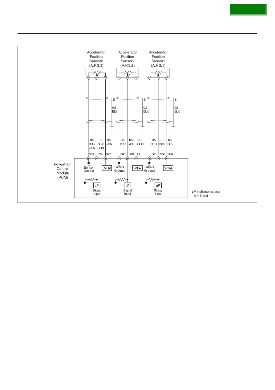
Circuit Description
D
The accelerator position (AP) sensor circuit provides a
voltage signal relative to accelerator pedal angle.
The accelerator pedal sensor (AP2) will vary about
87 % at idle position to about 13 % at wide open
throttle (WOT) to specified voltage (about 5V).
This code detects a correlation error betweenAPS2
and APS3.
Conditions for setting the DTC
D
The Ignition is “ON”.
D
The accelerator pedal angle difference is more than 4.5
% between ASP2 and APS3 for more than 265
millisecond.
Action Taken When the DTC Sets
D
The PCM will not turn the malfunction indicator lamp
(MIL) “ON”.
D
The PCM will store conditions which were present
when the DTC was set as Failure Records only. This
information will not be stored as Freeze Frame data.
Conditions for Clearing the MIL/DTC
D
The PCM will turn the MIL “OFF” on the third
consecutive trip cycle during which the diagnostic has
been run and the fault condition is no longer present.
D
A history DTC P1272 will clear after 40 consecutive trip
cycle during which the warm up cycles have occurred
without a fault.
D
DTC P1272 can be cleared using the Tech 2 “Clear
Info” function.
Diagnostic Aids
An intermittent may be caused by the following:
D
Poor connections.
D
Misrouted harness.
D
Rubbed through wire insulation.
D
Broken wire inside the insulation.
Check for the following conditions:
D
Poor connection at PCM-Inspect harness connectors
for backed out terminals, improper mating, broken
locks, improperly formed or damaged terminals, and
poor terminal to wire connection.
D
Damaged harness-Inspect the wiring harness for
damage. If the harness appears to be OK, observe the
AP sensor 2, AP sensor 3 display on the Tech 2 while
moving connectors and wiring harnesses related to the
sensor.
A change in the display will indicate the location of
the fault. If DTC P1272 cannot be duplicated, the
information included in the Failure Records data can
be useful in determined vehicle mileage since the
DTC was last set.
If it is determined that the DTC occurs intermittently,
performing the DTC
P1272 Diagnostic Chart may isolate the cause of the
fault.