Opel Frontera UE. Manual - part 1521


  Index      Opel     Opel Frontera UE - service repair manual 1999-2001 year


Search            


Content   ..  1519  1520  1521  1522   ..


Opel Frontera UE. Manual - part 1521


6E–299

6VD1 3.2L ENGINE DRIVEABILITY AND EMISSIONS

the condition that caused the DTC to be set occurs.  This
may assist in diagnosing the condition.

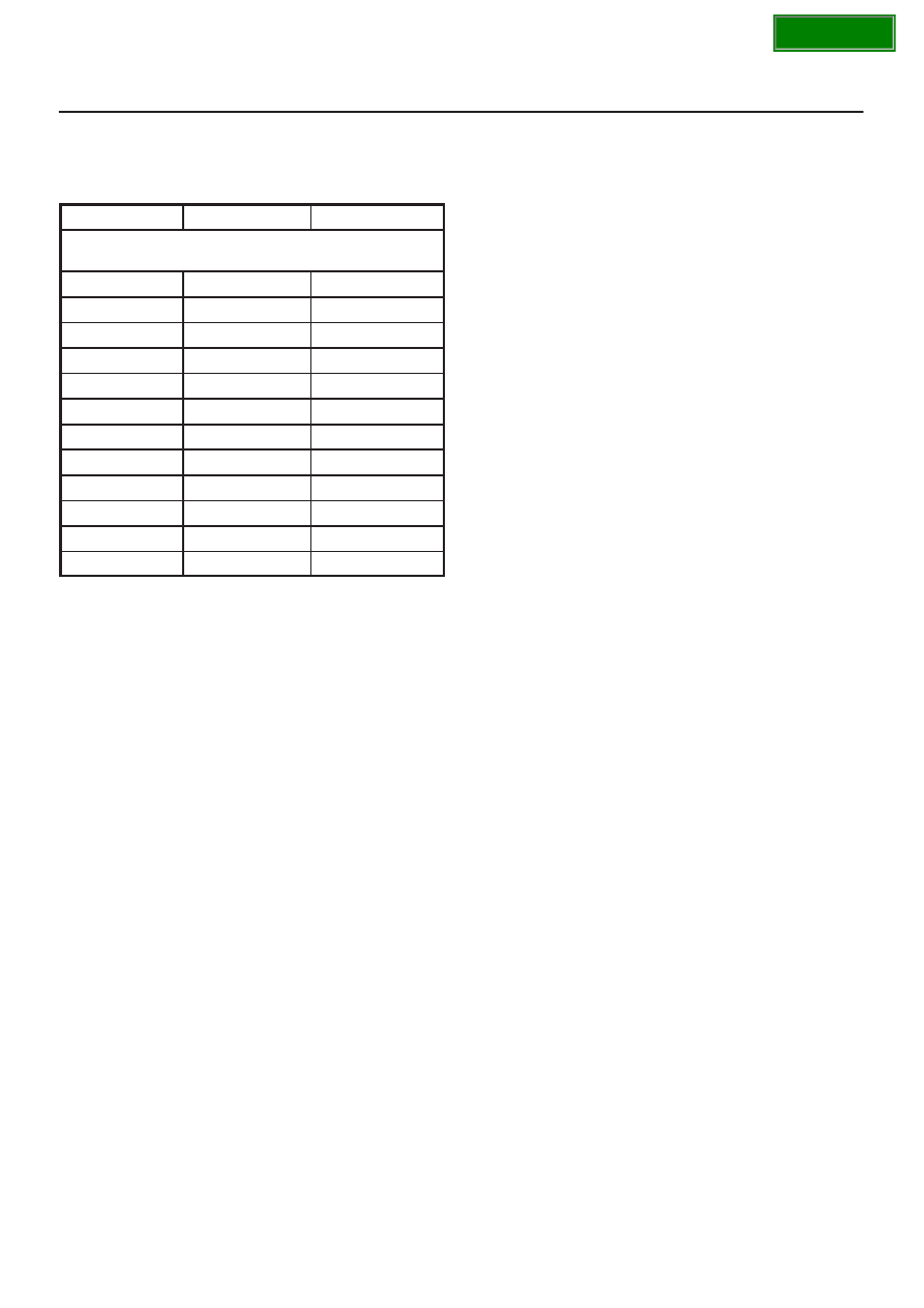
Engine Coolant Temperature Sensor

°

C

°

F

OHMS

Temperature vs. Resistance Values

(approximate)

100

212

177

80

176

332

60

140

667

45

113

1188

35

95

1802

25

77

2796

15

59

4450

5

41

7280

–5

23

12300

–15

5

21450

–30

–22

52700

–40

–40

100700

SECTION

6E–300

6VD1 3.2L ENGINE DRIVEABILITY AND EMISSIONS

DTC P1115 – ECT Sensor Circuit Intermittent High Voltage


Step

Action

Value(s)

Yes

No

1

Was the “On-Board Diagnostic (OBD) System Check”
performed?

Go to 

Step 2

Go to 

OBD

System

Check

2

Is DTC P0118 also set?

Go to 

DTC

P0118 chart

first

Go to 

Step 3

3

Is DTC P1111 also set?

Go to 

Step 8

Go to 

Step 4

4

1. Check for a poor sensor ground circuit terminal

connection at the ECT sensor.

2. If a problem is found, repair as necessary.

Was a problem found?

Verify repair

Go to 

Step 5

5

1. Check for a poor ECT signal circuit terminal

connection at the ECT sensor.

2. If a problem is found, repair as necessary.

Was a problem found?

Verify repair

Go to 

Step 6

6

1. Check the ECT signal circuit between the ECT

sensor connector and the PCM for an intermittent
open.

2. If a problem is found, repair as necessary.

Was a problem found?

Verify repair

Go to 

Step 7

7

1. Check the ECT signal circuit between the ECT

sensor connector and the PCM for an intermittent
short to voltage.

2. If a problem is found, repair as necessary.

Was a problem found?

Verify repair

Go to 

Step 8

8

1. Check for a poor sensor ground circuit terminal

connection at the PCM.

2. If a problem is found, repair as necessary.

Was a problem found?

Verify repair

Go to 

Step 9

9

1. Check for an intermittent open or a faulty splice in

the sensor ground circuit.

2. If a problem is found, repair as necessary.

Was a problem found?

Verify repair

Refer to

Diagnostic

Aids

SECTION

6E–301

6VD1 3.2L ENGINE DRIVEABILITY AND EMISSIONS

Diagnostic Trouble Code(DTC)

P1120-TPS 1 Throttle Position Sensor (TPS1) Output Abnormal

D06RY00111

Circuit Description

D

The throttle position (TP) sensor circuit provides a
voltage signal relative to throttle blade angle.
The TPS1 voltage will vary about 8% (0.4V) to about
92% (4.6V) at Wide Open Throttle (WOT) in the
specified voltage (about 5V).

This code detects a continuous short to ground or
high in either the circuit or the sensor.

Conditions for setting the DTC

D

The Ignition is “ON”.

D

The TPS1 output is more than 93.6 milliseconds, less
than 2.5% or more than 97.5% in the specified voltage
(5V).

Action Taken When the DTC Sets

D

The PCM will ON the MIL after second trip with
detected fault.

D

The PCM will store conditions which were present
when the DTC was set as Freeze Frame and in the
Failure Records data.

Conditions for Clearing the MIL/DTC

D

The PCM will turn the MIL “OFF” on the third
consecutive trip cycle during which the diagnostic has
been run and the fault condition is no longer present.

D

A history DTC P1120 will clear after 40 consecutive trip
cycle during which the warm up cycles have occurred
without a fault.

D

DTC P1120 can be cleared using the Tech 2 “Clear
Info” function.

Diagnostic Aids

An intermittent may be caused by the following:

D

Poor connections.

D

Misrouted harness.

D

Rubbed through wire insulation.

D

Broken wire inside the insulation.

Check for the following conditions:

D

Poor connection at PCM-Inspect harness connectors
for backed out terminals, improper mating, broken
locks, improperly formed or damaged terminals, and
poor terminal to wire connection.

D

Damaged harness-Inspect the wiring harness for
damage. If the harness appears to be OK, observe the
TPS 1 display on the Tech 2 while moving connectors
and wiring harnesses related to the sensor.
A change in the display will indicate the location of
the fault.

If DTC P1120 cannot be duplicated, the information
included in the Failure Records data can be useful in
determined vehicle mileage since the DTC was last
set.

SECTION

6E–302

6VD1 3.2L ENGINE DRIVEABILITY AND EMISSIONS

If it is determined that the DTC occurs intermittently,
performing the DTC P1120 Diagnostic Chart may
isolate the cause of the fault.

Diagnostic Trouble Code(DTC)P1120-TPS 1 Output Abnormal


Step

Action

Value(s)

Yes

No

1

Was the “On-Board(OBD)System Check” performed?

Go to

 Step 2

Go to

 OBD

System

Check

2

1. Ignition “ON”, engine not running.
2. Observe the MAP reading on the Tech 2.

Is the MAP reading less than the specified value?

65kPa

Go to

 Step 3

Go to

 Step 6

3

1. Disconnect the MAP sensor.
2. Connect a test 5 volt reference circuit and the MAP

signal at the MAP sensor harness connector.

3. Observe the MAP reading on the Tech 2.

Is the MAP reading less than the specified value? (If no,
start with diagnosis chart for other sensors in the circuit
and see if 5V returns.)

Go to

 Step 5

Go to

 Step 4

4

1. Check the MAP signal circuit between the PCM and

MAP shorted circuit.

2. If the MAP signal circuit is open or shorted, repair it

as necessary.

Was the MAP signal circuit open or shorted?

Verify repair

Go to 

Step 12

5

Replace the MAP sensor.

Is the action complete?

Verify repair

6

Observe the TP angle reading on the Tech 2 while
slowly opening the throttle.

Does the TP angle increase steadily and evenly from
the closed throttle value to the wide open throttle
value?

Throttle

Closed TPS1

8–10 % TPS2

8–10 % Wide

Open Throttle

TPS1 90–92

% TPS2

90–92 %

Refer to

Diagnostic

Aids

Go to

 Step 7

7

1. Disconnect the TP sensor.
2. Observe the TP sensor reading on the Tech 2.

Is the TP sensor reading near the specified value?

0V

Go to

 Step 8

Go to

 Step 9

8

1. Connect a test light between the 5Volt reference

circuit and the TP sensor signal circuit at the TP
sensor harness connector.

2. Observe the TP sensor reading on the Tech 2.

Is the TP sensor reading near the specified value?

5V

Go to

 Step 11

Go to

 Step 10

9

Check the following items;

1. TP1 signal circuit for a short to voltage.
2. TP1 sensor ground circuit for high resistance

between the PCM and the TP sensor.

3. TP1 sensor ground circuit for a poor connection.
4. If a problem is found, repair wiring harness as

necessary.

Was a problem found?

Verify repair

Go to

 Step 12

SECTION


Content   ..  1519  1520  1521  1522   ..