Content .. 1459 1460 1461 1462 ..
Opel Frontera UE. Manual - part 1461
6E–59
6VD1 3.2L ENGINE DRIVEABILITY AND EMISSIONS
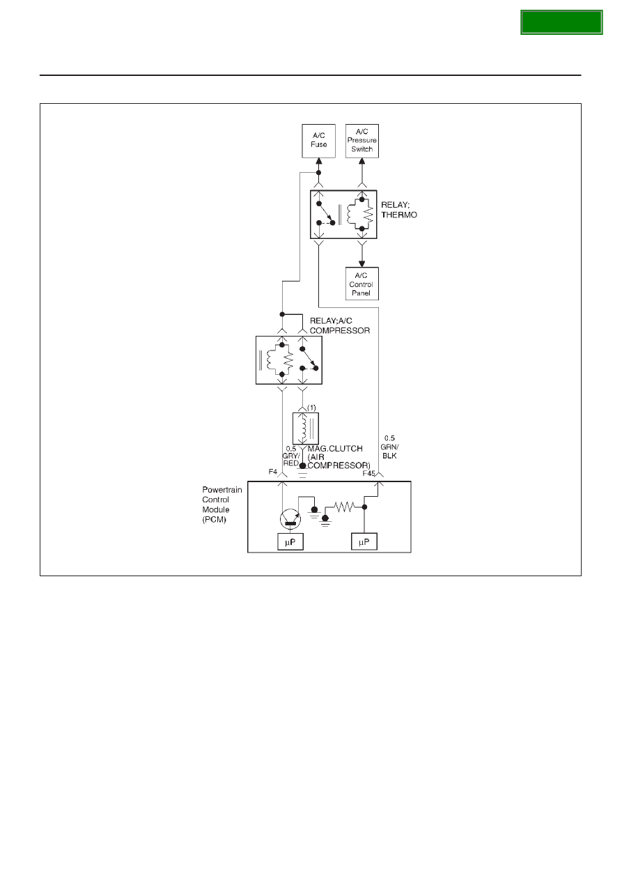
A/C Clutch Control Circuit Diagnosis
060R100063
Circuit Description
When air conditioning and blower fan are selected, and if
the system has a sufficient refrigerant charge, a 12-volt
signal is supplied to the A/C request input of the
powertrain control module (PCM). The A/C request
signal may be temporarily canceled during system
operation by the electronic thermostat in the evaporator
case. When the A/C request signal is received by the
PCM, the PCM supplies a ground from the compressor
clutch relay if the engine operating conditions are within
acceptable ranges. With the A/C compressor relay
energized, voltage is supplied to the compressor clutch
coil.
The PCM will enable the compressor clutch to engage
whenever A/C has been selected with the engine running,
unless any of the following conditions are present:
D
The ignition voltage is below 10.5 volts.
D
The engine coolant temperature (ECT) is greater
than 119
°
C (246
°
F).
D
The intake air temperature (IAT) is less than 5
°
C
(41
°
F).
D
The power steering pressure switch signals a high
pressure condition during 3 seconds after ignition
“ON”.
Diagnostic Aids
To diagnose an the intermittent fault, check for following
conditions:
D
Poor connection at the PCM–Inspect connections for
backed-out terminals, improper mating, broken locks,
improperly formed or damaged terminals, and poor
terminal-to-wire connection.
D
Damaged harness–Inspect the wiring harness for
damage. If the harness appears to OK, observe the
A/C clutch while moving connectors and wiring
harnesses related to the A/C. A sudden clutch
malfunction will indicate the source of the intermittent
fault.