Content .. 1449 1450 1451 1452 ..
Opel Frontera UE. Manual - part 1451
6E–19
6VD1 3.2L ENGINE DRIVEABILITY AND EMISSIONS
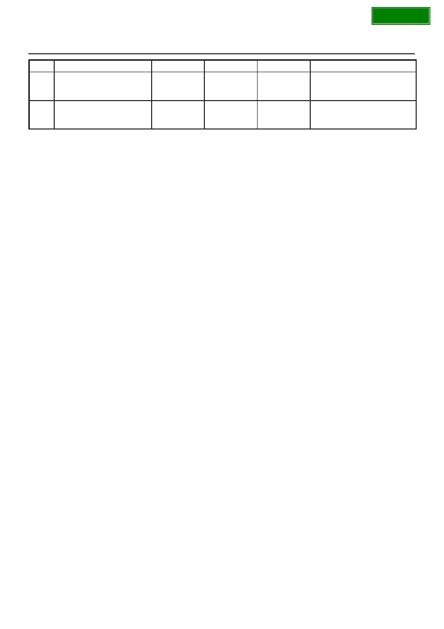
PIN
Refer To
ENG RUN
IGN ON
Wire Color
PIN Function
S19
ION Sensing Module
RED/YEL
1.555V
1.555V
General Description and
Operation, ION Sensing
Module
S20
Transmission Fluid
Temperature Sensor
Ground
RED/WHT
0.0V
0.0V
4L30E T/Mission