Index Opel Opel Frontera UE - service repair manual 1999-2001 year
Search
Content .. 1447 1448 1449 1450 ..
Opel Frontera UE. Manual - part 1449
6E–11
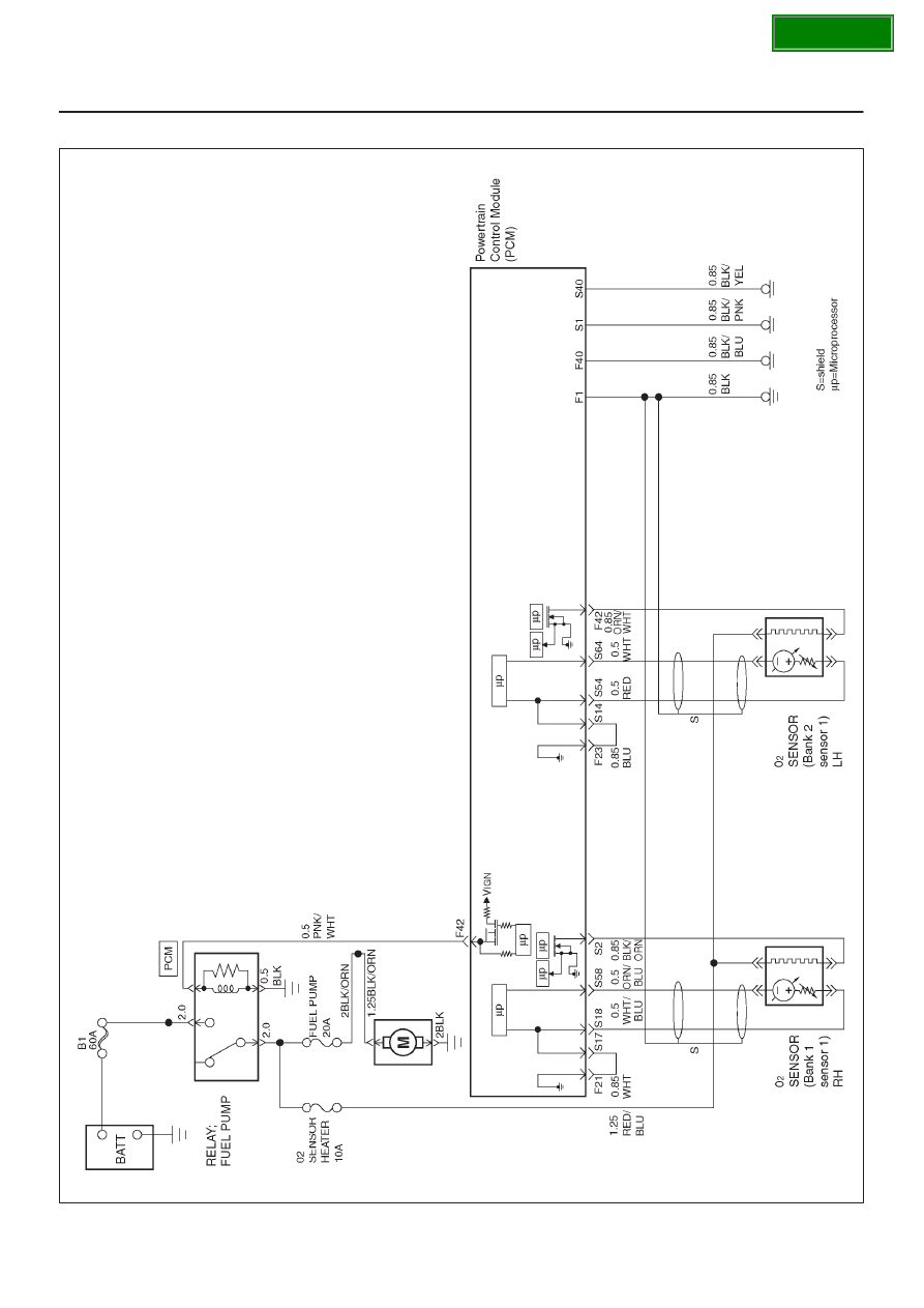
6VD1 3.2L ENGINE DRIVEABILITY AND EMISSIONS
PCM Wiring Diagram (6 of 7)
060R100125
SECTION