Content .. 1443 1444 1445 1446 ..
Opel Frontera UE. Manual - part 1445
6D3–21
STARTING AND CHARGING SYSTEM (6VD1 3.2L)
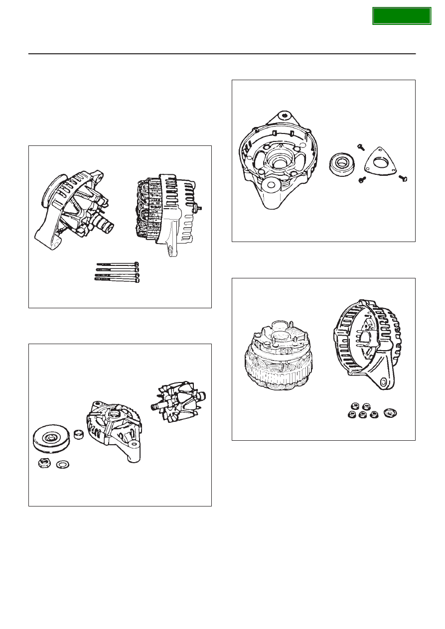
Disassembly
1. Remove the through bolt.
Insert the tip of a pry bar into the gaps between the
front cover and the stator core.
Pry apart and separate the front cover, rotor, the rear
cover and stator.
NOTE: Take care not to scratch or otherwise damage the
stator coil with pry bar.
F06RT021
2. Clamp the rotor in a vise and then remove the nut and
pulley.
3. Remove the rotor assembly from front cover.
F06RT022
4. Remove screws with bearing retainer from front cover
and remove bearing.
F06RT023
5. Remove the mounting nuts holding the “B” terminal,
the diode, and the brush holder.
6. Separate the rear cover from the stator.
F06RT024