Opel Frontera UE. Manual - part 1423


  Index      Opel     Opel Frontera UE - service repair manual 1999-2001 year


Search            


Content   ..  1421  1422  1423  1424   ..


Opel Frontera UE. Manual - part 1423


6A–69

ENGINE MECHANICAL (6VD1 3.2L)

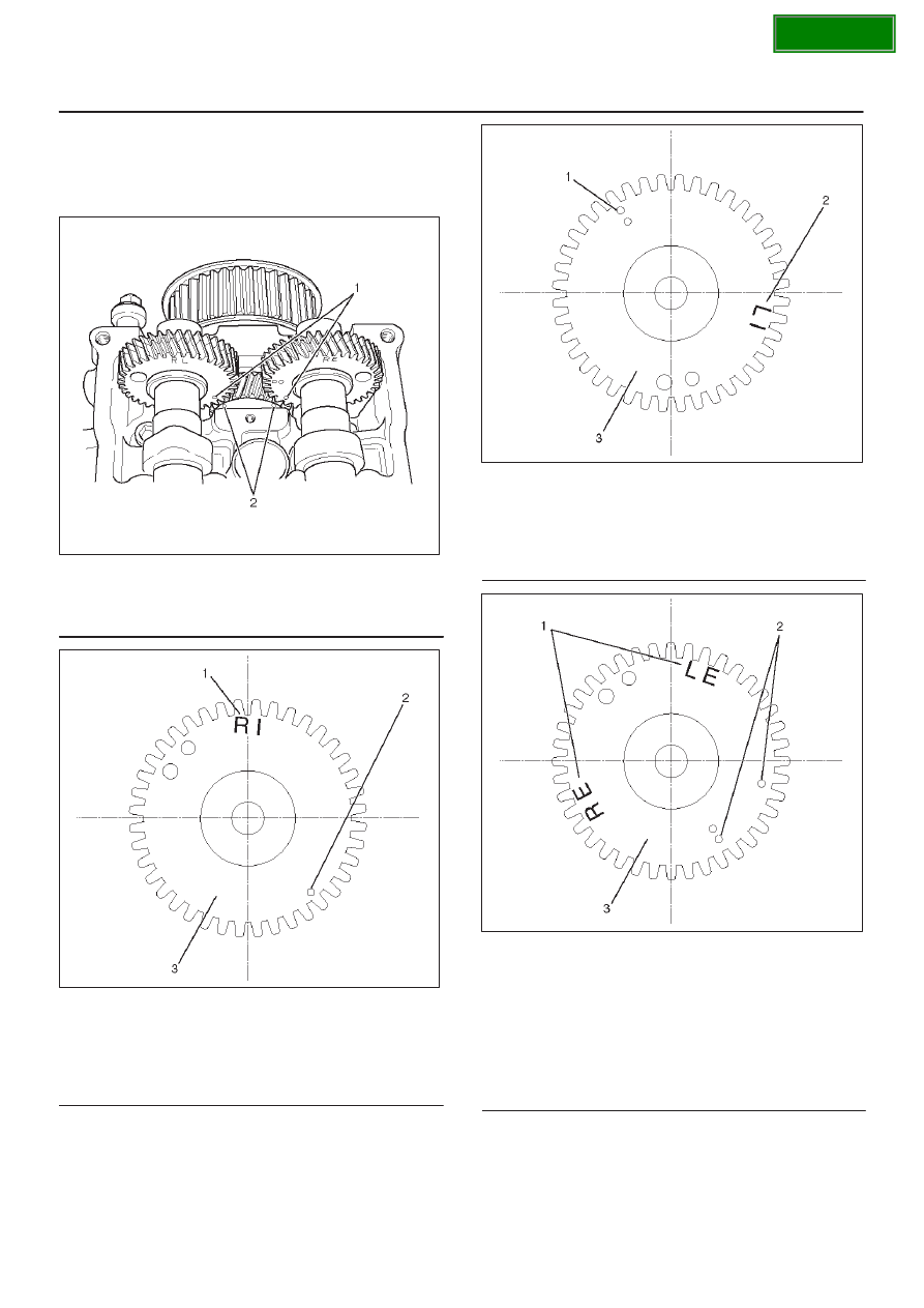
b. Align timing mark on intake camshaft (one dot for

right bank, two dots for left bank) and exhaust
camshaft (one dot for right bank, two dots for left
bank) to timing mark on camshaft drive gear (one
dot).

014R100016

Legend

(1) Alignment Mark on the Camshaft Gear
(2) Alignment Mark on the Camshaft Drive Gear

014R100025

Legend

(1) Discrimination Mark for Right Bank Intake

Camshaft Gear

(2) Alignment Mark for Right Bank (One Dot)
(3) Camshaft Timing Gear for Right Bank Intake

014R100026

Legend

(1) Alignment Mark for Left Bank (Two Dots)
(2) Discrimination Mark for Left Bank Intake

Camshaft Gear

(3) Camshaft Timing Gear for Left Bank Intake

014R100027

Legend

(1) Discrimination Mark

LE : Left Bank Exhaust
RE : Right Bank Exhaust

(2) Alignment Mark

One Dot for Right Bank
Two Dots for Left Bank

(3) Camshaft Timing Gear for Exhaust

SECTION

6A–70

ENGINE MECHANICAL (6VD1 3.2L)

014R100023

Legend

(1) Timing Mark on the Camshaft Drive Gear for

Right Bank Exhaust Camshaft

(2) Timing Mark on the Camshaft Drive Gear for

Right Bank Intake Camshaft

(3) Dowel Pin

014R100024

Legend

(1) Timing Mark on the Camshaft Drive Gear for

Left Bank Intake Camshaft

(2) Timing Mark on the Camshaft Drive Gear for

Left Bank Exhaust Camshaft

(3) Dowel Pin

c. Tighten twenty bolts in numerical order on one side

bank as shown in the illustration.

Torque: 10 N·m (1.0 kg·m/87 lb in)

014RW031

8. If the oil seal requires replacement, use the

5–8840–2445–0 to install the oil seal.

014RW034

SECTION

6A–71

ENGINE MECHANICAL (6VD1 3.2L)

9. If the camshaft end plug requires replacement, use

the 5–8840–2445–0 to install the camshaft end plug.

014R100031

10. Tighten bolt for camshaft drive gear pulley to the

specified torque using the 5–8840–2447–0 universal
holder.

Torque: 98 N·m (10.0 kg·m/72 lb ft)

014RW060

SECTION

6A–72

ENGINE MECHANICAL (6VD1 3.2L)

Crankshaft

Crankshaft and Associated Parts

013RW009

Legend

(1) Cylinder Head Assembly
(2) Crankcase with Oil Pan
(3) Oil Pipe and O-Ring
(4) Oil Strainer and O-Ring
(5) Oil Pump Assembly
(6) Cylinder Block Side  Bolts
(7) Oil Gallery

(8) Piston and Connecting Rod Assembly
(9) Flywheel

(10) Rear Oil Seal Retainer and Oil Seal

(11) Main Bearing Cap

(12) Crankshaft
(13) Main Bearing Cap Fixing Bolts
(14) Oil Gallery Fixing Bolts

Disassembly

1. Remove cylinder head assembly (1). Refer to

“Cylinder Head” in this manual.

2. Remove crankcase with oil pan (2). Refer to “Oil Pan

and Crankcase” in this manual.

CAUTION: Take care not to damage or deform the
sealing flange surface of crankcase.

3. Remove oil pipe and O-ring (3).
4. Remove oil strainer and O-ring (4).
5. Remove oil pump assembly (5).
6. Remove crankcase side bolts (6).

SECTION


Content   ..  1421  1422  1423  1424   ..