Opel Frontera UE. Manual - part 140


  Index      Opel     Opel Frontera UE - service repair manual 1999-2001 year


Search            


Content   ..  138  139  140  141   ..


Opel Frontera UE. Manual - part 140


POWER-ASSISTED BRAKE SYSTEM

5C–45

306RW005

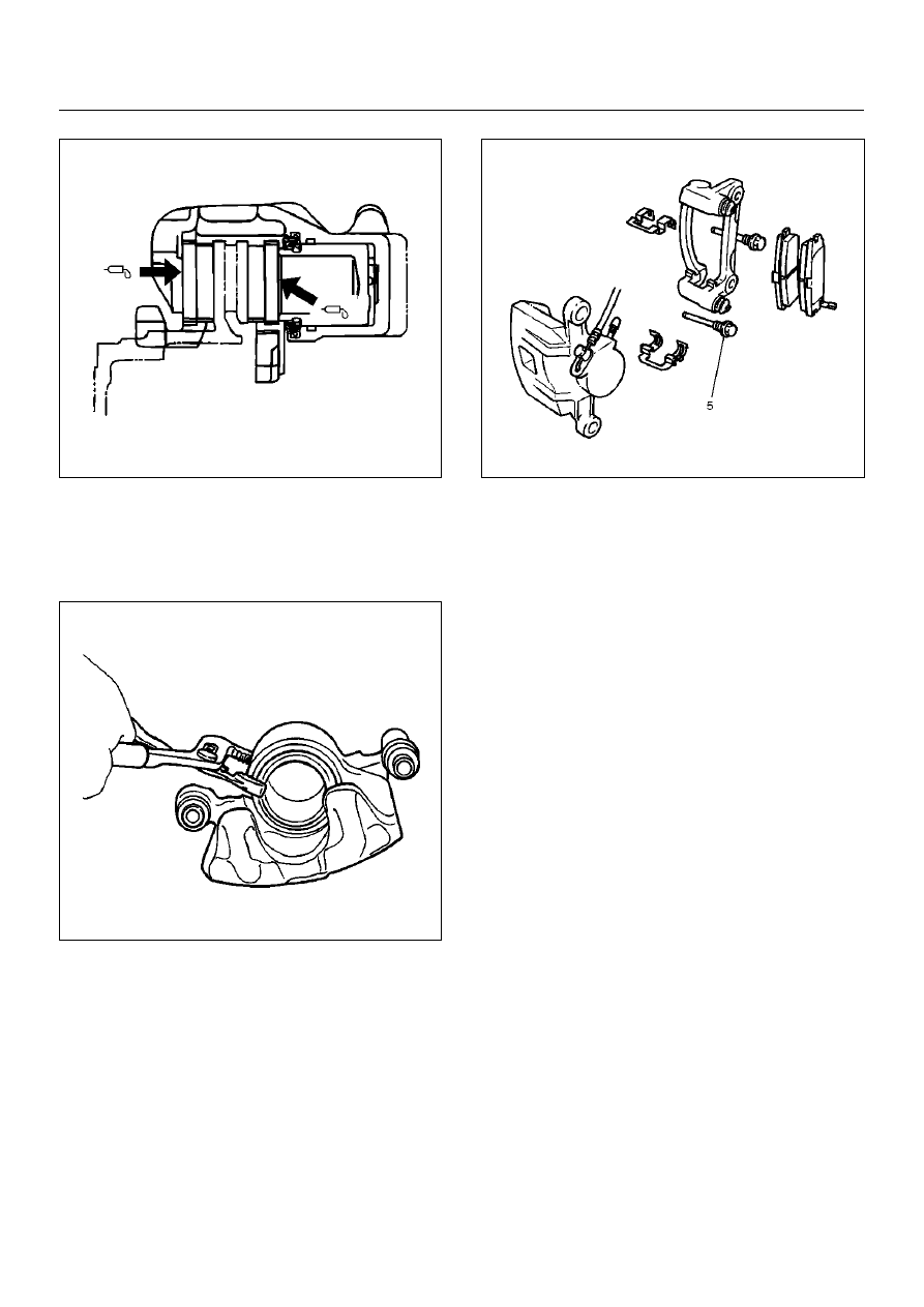
3. Use adjustable pliers to bottom the piston into the 

caliper bore. Be careful not to damage the piston 
dust boot and do not damage the flexible hose by 
twisting or pulling it. Install caliper assembly.
Set caliper assembly in place.

302RS008

4. Install lock bolt (5) and tighten the bolt to the 

specified torque.

Torque: 43 N·m (4.4 kg·m/32 lbft)

5. Install wheel and tire assembly, referring to “Wheels 

and Tires System" in Section 3E.

6. Pump the brake pedal several times to make sure 

that the pedal is firm.  Check the brake fluid level in 
the reservoir after pumping the brakes.

306RW006

5C–46

POWER-ASSISTED BRAKE SYSTEM

Rear Disc Brake Rotor

Inspection

In the manufacturing of the brake rotor, all the 
tolerances regarding surface finish, parallelism and 
lateral runout are held very closely. Maintaining these 
tolerances provides the surface necessary to assure 
smooth brake operation.

Lateral Runout

Lateral runout is the movement of the rotor from side to 
side as it rotates on the spindle. This could also be 
referred to as “rotor wobble".
This movement causes the piston to be knocked back 
into its bore. This results in additional pedal travel and a 
vibration during braking.

Checking Lateral Runout

1. Adjust the wheel bearing correctly. Refer to Drive 

Shaft System section.

2. Attach a dial indicator to some portion of the 

suspension so that the stem contacts the rotor face 
about 29 mm (1.14 in) from the rotor edge.

3. Move the rotor one complete rotation.

The lateral runout should not exceed 0.13 mm 
(0.005 in)

Maximum runout: 0.13 mm (0.005 in)

411RS019

Parallelism

Parallelism is the measurement of thickness of the rotor 
at four or more points around the circumference of the 
rotor. All measurement must be made at 22 mm (0.87 
in) from the edge of the rotor.
The rotor thickness must not vary more than 0.010 mm 
(0.0004 in) from point to point.

Maximum parallelism: 0.010 mm (0.0004 in)

420RS013

Replacing Brake Rotors

When installing new brake rotors, do not refinish the 
surfaces. These parts are at the correct level of surface 
finish.

Refinishing Brake Rotors

Accurate control of the rotor tolerances is necessary for 
proper performance of the disc brakes. Machining of the 
rotor should be done only with precision equipment. All 
brake rotors have a minimum thickness dimension cast 
into them.  This dimension is the minimum wear 
dimension and not a refinish dimension.  The minimum 
wear dimension is 16.6 mm (0.654 in). The minimum 
refinish dimension is 16.97 mm (0.668 in).
When refinishing rotors, always use sharp cutting tools 
or bits. Dull or worn tools leave a poor surface finish 
which will affect initial braking performance. Vibration 
dampening attachments should always be used when 
refinishing braking surfaces. These attachments 
eliminate tool chatter and will result in better surface 
finish.
After refinishing, replace any rotor that does not meet 
the minimum thickness of 16.97 mm (0.668 in). Do not 
use a brake rotor that will not meet the specification.

Minimum wear dimension: 16.6 mm (0.654 in)

Refinish dimension: 16.97 mm (0.668 in)

POWER-ASSISTED BRAKE SYSTEM

5C–47

420RW002

Rear Drum (In Disc) Inside Diameter 
Check

Check the rear drum inside diameter by measuring at 
more than two portions as shown in the illustration.
If the inside diameter is greater than the limit, replace 
the rear rotor.

Standard: 210.0 mm (8.27 in)

Limit: 211.4 mm (8.32 in)

420RS035

5C–48

POWER-ASSISTED BRAKE SYSTEM

Rear Disc Brake Caliper Assembly

Rear Disc Brake Caliper Assembly and Associated Parts

306RW007

Legend

EndOFCallout

Removal

1. Raise the vehicle and support with suitable safety 

stands.

2. Remove wheel and tire assembly, referring to 

“Wheels and Tires System" in Section 3E.

3. Remove the bolt and gaskets, then disconnect the 

flexible hose from the caliper and after 
disconnecting the flexible hose (1), cap or tape the 
openings to prevent entry of foreign material.

306RW008

4. Since the brake fluid flows out from the connecting 

coupler, place a drain pan under the vehicle.

5. Remove lock bolt (3).

(1) Brake Flexible Hose
(2) Clip
(3) Lock Bolt
(4) Support Bracket

(5) Guide Bolt
(6) Pad Assembly with Shim
(7) Caliper Assembly


Content   ..  138  139  140  141   ..