Opel Frontera UE. Manual - part 138


  Index      Opel     Opel Frontera UE - service repair manual 1999-2001 year


Search            


Content   ..  136  137  138  139   ..


Opel Frontera UE. Manual - part 138


POWER-ASSISTED BRAKE SYSTEM

5C–37

4. Since the brake fluid flows out from the connecting 

coupler, place a drain pan under the vehicle.

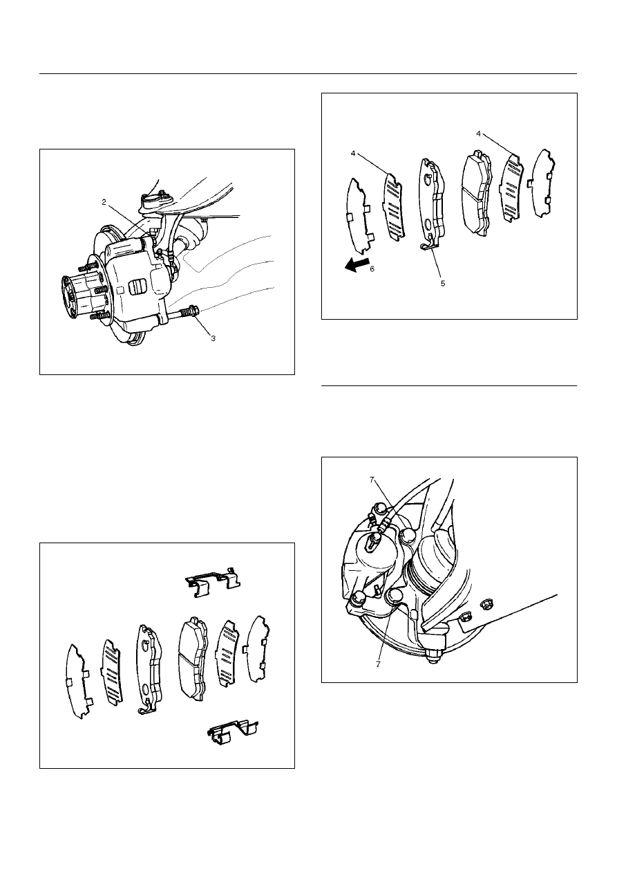
5. Remove guide bolt (2).

6. Remove lock bolt (3).

302RW010

7. Remove caliper assembly.

8. Remove support bracket with pad assembly and 

take care not to damage the flexible brake hose 
when removing the support bracket.

9. Remove pad assembly with shim and mark the 

lining locations if they are to be reinstalled.

10. Remove clip.

Installation

1. Install clip.

302RS005

2. Apply special grease (approximately 0.2 g) to both 

contacting surfaces of the inner shims (4). Wipe off 
extruded grease after installing. Install pad 
assembly with shim.

302RW011

Legend

EndOFCallout

3. Install support bracket and tighten the bolt (7) to the 

specified torque.

Torque: 155 N·m (15.8 kg·m/115 lbft)

302RW012

4. Install caliper assembly.

5. Install lock bolt (9) and guide bolt (8) and tighten the 

bolt to the specified torque.

Torque: 74 N·m (7.5 kg·m/54 lbft)

(4) Inner Shim
(5) Wear Indicator
(6) Inner Side

5C–38

POWER-ASSISTED BRAKE SYSTEM

302RW013

6. Install brake flexible hose, always use new gaskets 

and be sure to put the hooked edge of the flexible 
hose end into the anti–rotation cavity then tighten 
the I–bolt (10) to the specified torque.

Torque: 34 N·m (3.5 kg·m/25 lbft)

302RW014

7. Install wheel and tire assembly, referring to “Wheels 

and Tires System" in Section 3E.

8. Bleed  brakes. Refer to “Hydraulic Brakes" in this 

section.

POWER-ASSISTED BRAKE SYSTEM

5C–39

Front Disc Brake Caliper

Front Disc Brake Caliper Disassembled View

302RW015

Legend

EndOFCallout

Disassembly

1. Remove guide bolt.

2. Remove lock bolt.

3. Remove dust boot: guide bolt and lock bolt.

(1) Guide Bolt
(2) Lock Bolt
(3) Bleeder with Cap
(4) Caliper Body
(5) Dust Boot: Guide Bolt and Lock Bolt

(6) Piston Seal
(7) Piston
(8) Dust Boot: Piston
(9) Dust Boot Ring

5C–40

POWER-ASSISTED BRAKE SYSTEM

4. Remove dust boot ring, using a small screwdriver.

302RS016

5. Insert a block of wood into the caliper and force out 

the piston by blowing compressed air into the caliper 
at the flexible hose attachment. This procedure must 
be done prior to removal of the dust boot.
Remove piston.

WARNING:  Do not place your fingers in front of the 
piston in an attempt to catch or protect it when 
applying compressed air.  This could result in 
personal injury.

CAUTION:  Use just enough air to ease the piston 
out of the bore. If the piston is blown out, it may be 
damaged.

302RS017

6. Remove dust boot: piston.

7. Remove piston seal.

8. Remove bleeder with cap.

9. Remove caliper body.

Inspection and Repair

Make necessary parts replacement, if wear, damage, 
corrosion or any other abnormal conditions are found 
through inspection.
Check the following parts:

• Rotor

• Cylinder body

• Cylinder bore

• Piston

• Guide bolt, lock bolt

• Support bracket

NOTE:  The piston seal, boot ring and dust boot are to 
be replaced each time the caliper is overhauled. Discard 
these used rubber parts and replace them with new 
ones.

Reassembly

1. Install caliper body.

2. Install bleeder with cap and tighten the cap to the 

specified torque.

Torque: 8 N·m (0.8 kg·m/69 lbin)

3. Apply special rubber grease to the piston seal and 

cylinder wall, then insert the piston seal into the 
cylinder. The special rubber grease is included in 
the repair kit.

302RS018

4. When inserting the piston into the cylinder, use 

finger pressure only and do not use a mallet or other 
impact tool, since damage to the cylinder wall or 
piston seal can result.
Install piston.


Content   ..  136  137  138  139   ..