Opel Frontera UE. Manual - part 1369


  Index      Opel     Opel Frontera UE - service repair manual 1999-2001 year


Search            


Content   ..  1367  1368  1369  1370   ..


Opel Frontera UE. Manual - part 1369


4D2–11

TRANSFER CASE (TOD)

2. Install the plate, bracket, connector bracket and

ground cable of the harness assembly, and tighten
the transfer cover retaining bolts (16 pieces) to
specified torque.

Torque: 31 N·m (23 lb ft)

261RY00035

261RY00037

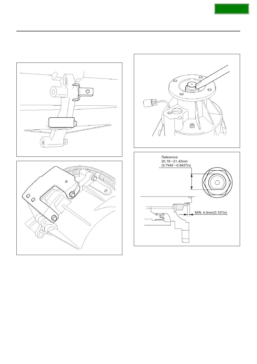
3. Install the front and rear companion flange.
4. Install the oil seal and washer, and using the flange

holder J–8614–11, install the new end nut to the
specified torque.

Torque: 167 N·m (123 lb ft)

5. Securely stake the end nut at one spot.

NOTE: Be sure to confirm that there is no clack at the
staked portion of the end nut after staking.

266RY00003

266R200004

SECTION

4D2–12 TRANSFER CASE (TOD)

6. Apply recommended liquid gasket (LOCTITE 598 or

its equivalent) to the transfer cover and shift motor
assembly fitting surface.

261R200003

7. Install the shift motor assembly to the transfer cover

assembly.

Torque: 10 N·m (87 lb in)

8. Install the 4H and 4L switch.

Torque: 24 N·m (17 lb ft)

9. Install the harness assembly and shift motor harness

connector to the connector bracket.

10. Install the front and rear speed sensors to the transfer

cover.

Torque: 5 N·m (43 lb in)

11. Connect the harness assembly connector to the

clutch solenoid coil harness connector and 4H and 4L
switch.

D

Fix the harness with harness bracket.

261RY00009

12. Install the driven gear and speedometer sensor to the

transfer case.

Torque: 25 N·m (19 lb ft)

261RY00034

13. Remove the filler plug and fill the transfer case with

ATF DEXRON

–II or III.

14. Wind the sealing tape around the filler plug thread and

tighten the plug to the specified torque.

Torque: 25 N·m (19 lb ft)

261RY00026

15. Install the breather hose to the transfer case.

SECTION

4D2–13

TRANSFER CASE (TOD)

Transfer Cover Assembly

261RY00032

Legend

(1) Coil Assembly
(2) Snap Ring
(3) Ball Bearing

(4) Speed Gear and Tone Wheel
(5) Ball Bearing
(6) Transfer Cover (With Oil Seal)
(7) Oil Drain Plug and Oil Filler Plug

Disassembly

1. Using a precision screwdriver or a suitable tool, push

down the lock to unlatch the terminal for the coil
assembly, and pull the terminal out.

NOTE: Use care to prevent damage to harness terminal
and connector.

261RY00013

SECTION

4D2–14 TRANSFER CASE (TOD)

2. Remove the coil assembly set nuts (3 pieces) and coil

assembly from the transfer cover.

261RW030

3. Using snap ring pliers, remove the snap ring from the

transfer cover.

261RW047

4. Strike the speed gear and tone wheel with a rod or

other appropriate tool from the rear side of the
transfer cover assembly, and remove the ball bearing,
speed gear and tone wheel.

NOTE: Use care to prevent damage to the speed gear
teeth.

261RY00012

5. Using the bearing remover J–42805 and slide

hammer J–2619–01, remove the ball bearing of the
front output shaft from the transfer cover.

261RY00027

Inspection and Repair

Refer to 

“Inspection and Repair (Transfer Case

Assembly)” in this section.

SECTION


Content   ..  1367  1368  1369  1370   ..