Opel Frontera UE. Manual - part 1362


  Index      Opel     Opel Frontera UE - service repair manual 1999-2001 year


Search            


Content   ..  1360  1361  1362  1363   ..


Opel Frontera UE. Manual - part 1362


4D1–24 TRANSFER CASE

(32) Bearing Snap Ring
(33) Counter Gear Assembly
(34) Snap Ring
(35) Ball Bearing
(36) Snap Ring
(37) Ball Bearing

(38) Spacer
(39) Belleville Spring
(40) Sub–Gear (anti–lash plate)
(41) Counter Gear
(42) Transfer Case (with oil seal)
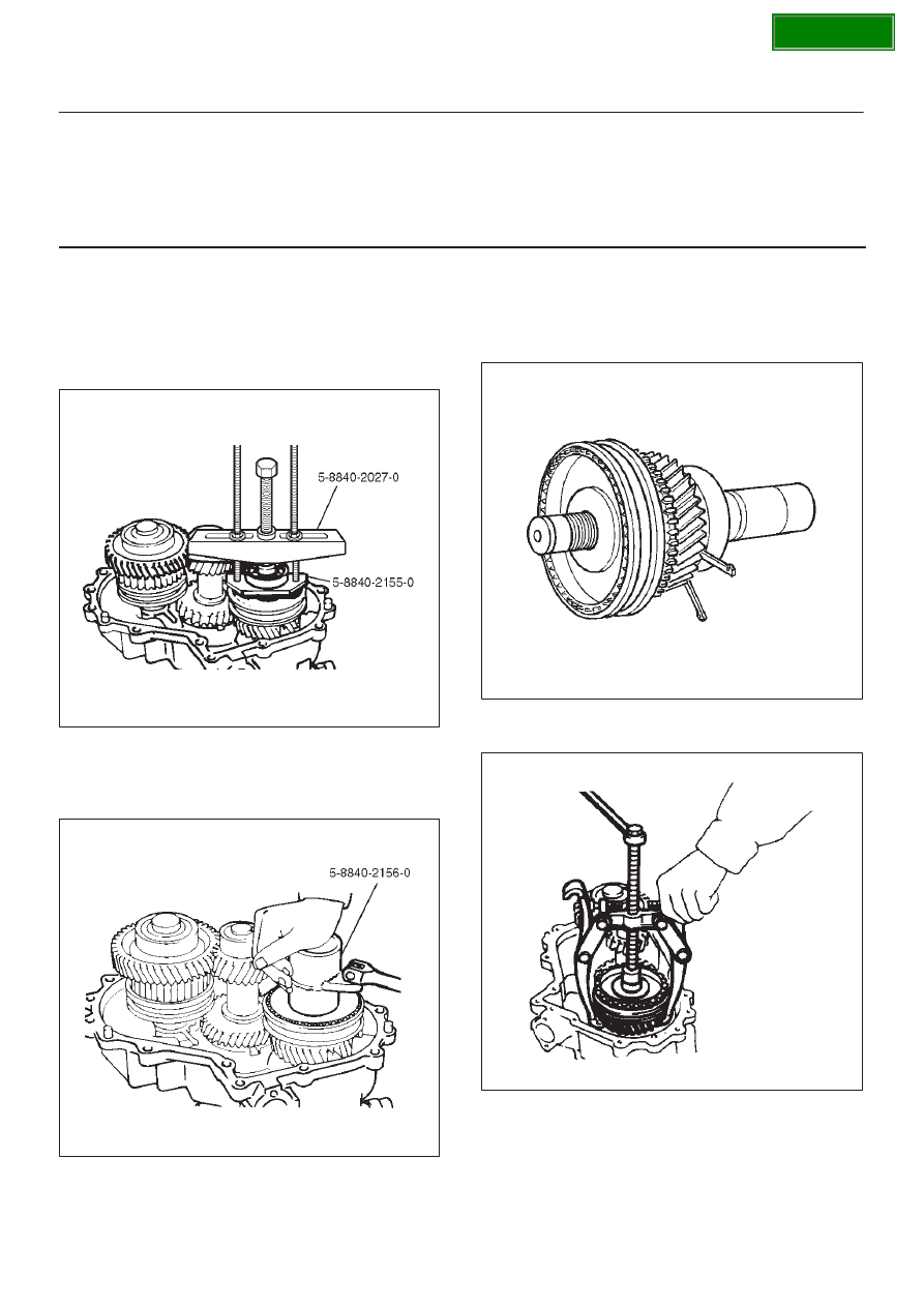
Disassembly

1. Use a pair of snap ring pliers to remove the snap ring

(1).

2. Use a bearing remover 5–8840–2155–0 and puller

5–8840–2027–0 to remove the ball bearing (2).

262RW069

3. Install the front companion flange temporarily.
4. Use the Companion flange holder 5–8840–0133–0

and lock nut wrench 5–8840–2156–0 to remove the
lock nut (3).

226RW190

5. Remove the front companion flange.
6. Remove snap ring (4). (A/T)
7. Remove the input shaft assembly (5) from the

transfer case (42). (A/T)

265RW001

8. Use the universal puller to remove the high–low

clutch hub and sleeve (6), and transfer input gear (7).

226RS070

SECTION

TRANSFER CASE 4D1–25

9. Remove needle bearing (8).

10. Remove bearing collar (9).

226RS071

11. Remove ball (10).

12. Remove plate (11).
13. Use a bench press and the ball bearing remover

5–8840–0015–0 to remove the ball bearing (12) from
the input shaft (13). (A/T)

265RW013

14. Use a pair of snap ring pliers to remove the bearing

snap ring (14).

15. Use a plastic hammer to tap the front output gear

assembly (15) free.

262RS009

16. Remove bearing snap ring (16).
17. Use a bench press and the bearing remover

5–8840–0015–0 to remove the following parts.

18. Remove ball bearing (17), and bearing collar (18).

Remove sub–gear snap ring (19), spacer (20),
belleville spring (21), and sub–gear (anti–lash plate)
(22). (M/T)
Remove front output gear (23) and needle bearing
(24).

262RW070

19. Remove inside ring (25).
20. Remove outside ring (26).
21. Remove block ring (27).
22. Use a bench press and bearing remover

5–8840–0015–0 to remove 2WD–4WD clutch hub
and sleeve assembly (28) and stopper plate (29).

NOTE: Do not reuse the stopper plate.

SECTION

4D1–26 TRANSFER CASE

23. Disassemble the 2WD–4WD clutch hub and sleeve

assembly (28).

D

Springs (1)

D

Inserts (2)

D

Clutch Hub (3)

D

Sleeve (4)

226RW133

24. Use a bench press and the ball bearing remover

5–8840–0015–0 to remove the ball bearing (30) from
front output shaft (31).

262RW071

25. Remove bearing snap ring (32).
26. Remove the counter gear assembly (33) from the

transfer case (42).

27. Use a pair of snap ring pliers to remove the snap ring

(34).

28. Use a bench press and the bearing remover

5–8840–0015–0 to remove the ball bearing (35).

29. Use a pair of snap ring pliers to remove the snap ring

(36).

30. Use a bench press and the bearing remover

5–8840–0015–0 to remove the ball bearing (37).

226RW208

31. Remove spacer (38).
32. Remove belleville spring (39).
33. Remove sub–gear (anti–lash plate) (40).
34. Remove counter gear (41).
35. Remove transfer case (with oil seal) (42), performing

the following steps  (M/T)

D

Cover the shaft splines with adhesive tape (43).

A07RW022

Legend

(43) Adhesive Tape
(44) Oil Seal Lip
(45) Oil Seal Collar
(46) Bearing

D

Remove the transfer case together with
intermediate plate with gear assembly from the
transmission case (M/T).

SECTION

TRANSFER CASE 4D1–27

D

Remove the transfer case from the intermediate
plat with gear assembly (M/T).

Inspection and Repair

1. Make the necessary repair or parts replacement if

wear, damage or any other abnormal conditions are
found during inspection.

2. Wash all parts thoroughly in clean solvent. Be sure all

old lubricant, metallic particles, dirt, or foreign
material are removed from the surfaces of every part.
Apply compressed air to each oil feed port and
channel in each case half to remove any obstructions
or cleaning solvent residue.

Gears

1. Inspect all the gear teeth for signs of excessive wear

or damage and check all the gear splines for burrs,
nicks, wear or damage. Remove the minor nicks or
scratches on an oil stone. Replace any part exhibiting
excessive wear or damage.

Front Output Gear Inside Diameter

1. Use an inside dial indicator to measure the gear inside

diameter.

2. If the measured value exceeds the specified limit, the

gear must be replaced.

Gear inside diameter

Standard : 48.000–48.013 mm (1.8898–1.8903 in)

Limit : 48.10 mm (1.894 in)

226RS040

Clutch Hub Spline Play

1. Set a dial indicator to the clutch hub to be measured.
2. Move the clutch hub as far as possible to both the right

and the left.
Note the dial indicator reading.

3. If the measured value exceeds the specified limit, the

clutch hub must be replaced.

Clutch hub spline play
Standard : 0–0.1 mm (0–0.004 in)
Limit : 0.2 mm (0.008 in)

226RS042

Bearings

1. Inspect the condition of all the needles and ball

bearings. Wash bearings thoroughly in a cleaning
solvent. Apply compressed air to the bearings.

NOTE: Do not allow the bearings to spin. Turn them
slowly by hand. Spinning bearings may damage the
rollers.

2. Lubricate the bearings with a light oil and check them

for roughness by slowly turning the race by hand.

Ball Bearing Play

1. Use a dial indicator to measure the ball bearing play.
2. If the measured value exceeds the specified limit, the

ball bearing must be replaced.

Limit : 0.2 mm (0.008 in)

226RS043

SECTION


Content   ..  1360  1361  1362  1363   ..