Content .. 1339 1340 1341 1342 ..
Opel Frontera UE. Manual - part 1341
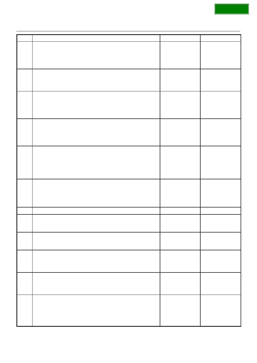
DRIVE LINE CONTROL SYSTEM (TOD)
4B2–104
Step
Action
Yes
No
1
Are the front and rear tires in specified size?
Go to
Step 2
Replace the tires
with specified
ones, and service
the new tires.
Go to
Step 16
2
Is the tire pressure correct?
Go to
Step 3
Inflate the tires
with specified
pressure.
Go to
Step 16
3
Are the tires free from abnormal wear?
Go to
Step 4
Replace the tires
with specified
ones, and service
the new tires.
Go to
Step 16
4
Are different types of tires used?
Go to
Step 5
Replace the tires
with specified
ones, and service
the new tires.
Go to
Step 16
5
1. Start the engine.
2. Select the TOD switch to the TOD position.
3. Fully turn the steering to the left (or right) end, and select the D
range and start the creep run.
Does the tight corner braking occur? Is the judder with chug-chug
sound observed? * Use caution on the operation.
Go to
Step 6
Go to
Step 11
6
1. Select the TOD switch to the 2H position.
2. Fully turn the steering to the left (or right) end, and select the D
range and start the creep run.
Does the tight corner braking occur? Is the judder with chug-chug
sound observed? * Use caution on the operation.
Go to
Step 7
Go to
Step 14
7
Is an LSD mounted to the rear differential?
Go to
Step 8
Go to
Step 9
8
Is the genuine LSD oil used in the rear differential?
Go to
Step 9
Replace the
differential oil.
Go to
Step 16
9
Does the engine output the power correctly?
Go to
Step 10
Check the
engine.
Go to
Step 16
10
Do the speed sensors work correctly? (Check trouble codes.)
The ECU has
failed. Replace
the ECU.
Go to
Step 16
Replace the
speed sensors.
Go to
Step 16
11
Is the tight corner braking observed only when the brake is
applied?
Go to
Step 12
Conduct full
steering under
WOT.
Go to
Step 5
12
1. Turn on the starter switch.
Is 8
∼
10 V observed between terminals 33 and 47?
Go to
Step 13
Repair the circuit
of the ECU
connector
terminal 33 (ABS
IN).
Go to
Step 16