Content .. 1326 1327 1328 1329 ..
Opel Frontera UE. Manual - part 1328
DRIVE LINE CONTROL SYSTEM (TOD)
4B2–52
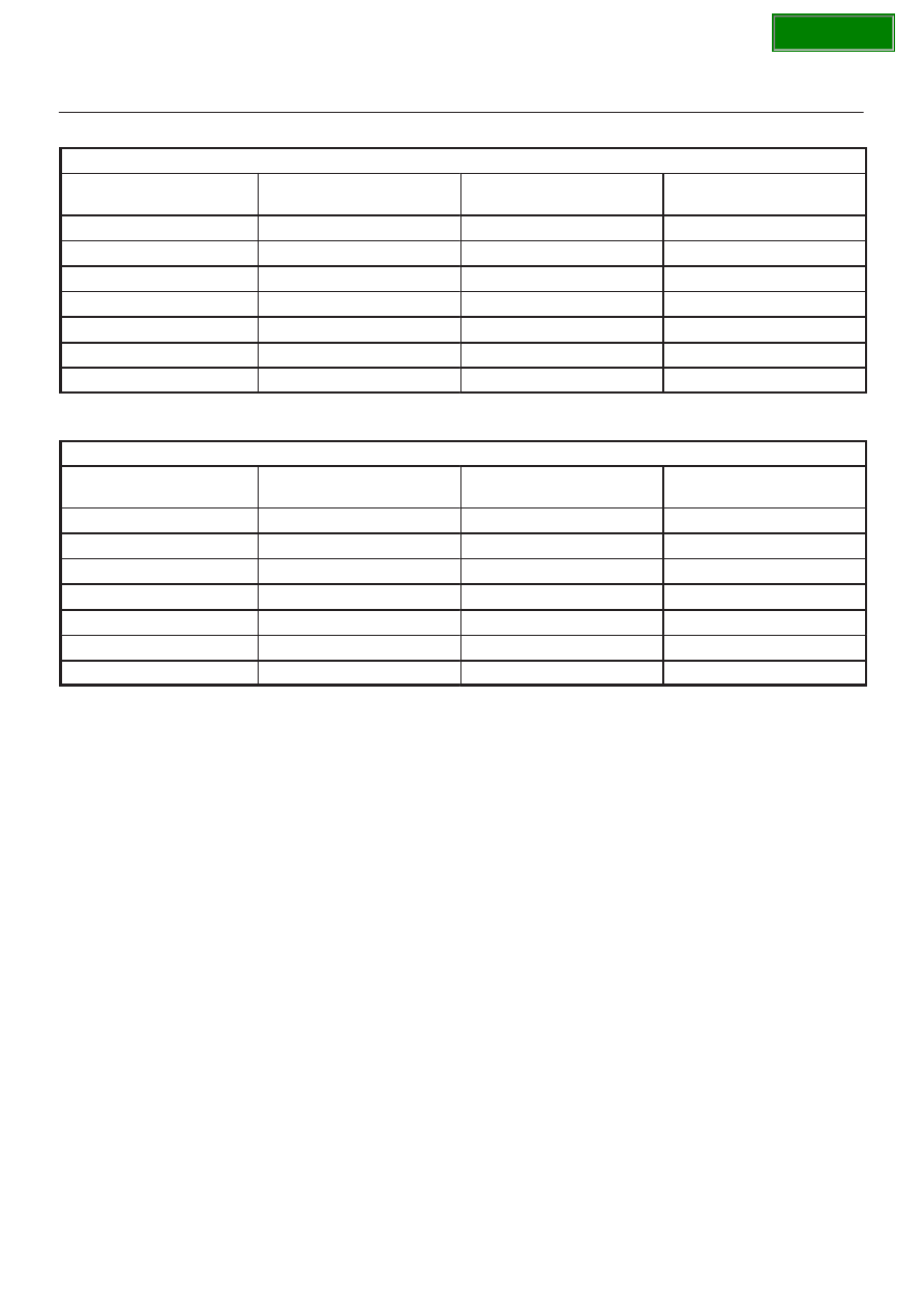
Table 1
Unit: V
AT selector position
Voltage between
terminal 28 and 47
Voltage between
terminal 41 and 47
Voltage between
terminal 27 and 47
P
12
0
0
R
12
12
0
N
0
12
0
D
0
12
12
3
12
12
12
2
12
0
12
1
0
0
12
Table 2
Continuity between terminals of inhibitor switch connector (E–41)
AT selector position
Continuity between
terminal 8(A) and 5(D)
Continuity between
terminal 7(B) and 5(D)
Continuity between
terminal 6(C) and 5(D)
P
YES
NO
NO
R
YES
YES
NO
N
NO
YES
NO
D
NO
YES
YES
3
YES
YES
YES
2
YES
NO
YES
1
NO
NO
YES