Opel Frontera UE. Manual - part 1284


  Index      Opel     Opel Frontera UE - service repair manual 1999-2001 year


Search            


Content   ..  1282  1283  1284  1285   ..


Opel Frontera UE. Manual - part 1284


WHEEL AND TIRE SYSTEM

3E–13

480RS013

Legend

EndOFCallout

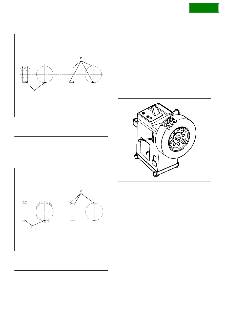
Dynamic balance is the equal distribution of weight on 
each side of the wheel center-line so that when the tire 
spins there is no tendency for the assembly to move 
from side to side.   Assemblies that are dynamically 
unbalanced may cause shimmy.

480RS014

Legend

EndOFCallout

WARNING:  STONES SHOULD BE REMOVED FROM 
THE TREAD TO AVOID OPERATOR INJURY DURING 
SPIN BALANCING AND TO OBTAIN A GOOD 
BALANCE.

Balancing Wheel and Tire

On-vehicle Balancing

On-Vehicle balancing methods vary with equipment and 
tool manufacturers.   Be sure to follow each 
manufacturer's instructions during balancing operation.

Off-vehicle Balancing

Most electronic off-vehicle balancers are more accurate 
than the on-vehicle spin balancers.   They are easy to 
use and give a dynamic balance.  Although they do not 
correct for drum or disc unbalance (as on- vehicle spin 
balancing does),  they are very accurate.

480RS015

(1) Heavy Spot Wheel Shimmy
(2) Add Balance Weights Here

(1) Heavy Spot Wheel Hop
(2) Add Balance Weights Here

SECTION

3E–14

WHEEL AND TIRE SYSTEM

Main Data and Specifications

General Specifications

Torque Specifications

E03RX008

Wheels

Size

15 x 6.5JJ

Offset

38.0mm (1.50 in)

P.C.D., wheel studs

139.7mm (5.50in)

Standard tire

Size

P235/75R15

Pressure(Front)

200kPa (2.0kg/cm

2

,29psi)

Pressure(Rear)

200kPa (2.0kg/cm

2

,29psi)

SECTION

INTELLIGENT SUSPENSION

3F–1

FRONTERA

SUSPENSION

INTELLIGENT SUSPENSION CONTROL

CONTENTS

Service Precaution

3F–2

. . . . . . . . . . . . . . . . . . . . . . 

General Description

3F–2

. . . . . . . . . . . . . . . . . . . . . 

PIN ASSIGNMENT TABLE

3F–4

. . . . . . . . . . . . . 

System Components

3F–4

. . . . . . . . . . . . . . . . . . . 

Control Unit

3F–4

. . . . . . . . . . . . . . . . . . . . . . . . . . . 

Actuator

3F–4

. . . . . . . . . . . . . . . . . . . . . . . . . . . . . . 

Adjustable Damping Force Shock Absorber

3F–4

Warning Lamp

3F–4

. . . . . . . . . . . . . . . . . . . . . . . . 

Vertical G-Sensor

3F–5

. . . . . . . . . . . . . . . . . . . . . . 

Lateral G-Sensor

3F–5

. . . . . . . . . . . . . . . . . . . . . . 

Acronyms and Abbreviations

3F–5

. . . . . . . . . . . . 

General Diagnosis

3F–5

. . . . . . . . . . . . . . . . . . . . . . . 

General Information

3F–5

. . . . . . . . . . . . . . . . . . . . 

Service Precautions

3F–5

. . . . . . . . . . . . . . . . . . . 

Computer System Service Precautions

3F–5

. . . 

General Service Precautions

3F–5

. . . . . . . . . . . . 

Parts Handling

3F–5

. . . . . . . . . . . . . . . . . . . . . . . . 

FLASHING CODES

3F–6

. . . . . . . . . . . . . . . . . . . . 

CLEAR DTC

3F–7

. . . . . . . . . . . . . . . . . . . . . . . . . . 

INTERMITTENT CONDITIONS

3F–8

. . . . . . . . . 

BULB CHECK

3F–8

. . . . . . . . . . . . . . . . . . . . . . . . . 

DTC CHECK

3F–8

. . . . . . . . . . . . . . . . . . . . . . . . . . 

Basic Diagnosis Flow

3F–9

. . . . . . . . . . . . . . . . . . 

Circuit Diagram

3F–10

. . . . . . . . . . . . . . . . . . . . . . . 

Parts Location

3F–13

. . . . . . . . . . . . . . . . . . . . . . . . 

Connector List

3F–14

. . . . . . . . . . . . . . . . . . . . . . . . 

Diagnostic Trouble Code (DTC)
 Identification

3F–16

. . . . . . . . . . . . . . . . . . . . . . . . . 

DTC2 Actuator Coil Over Current

3F–17

. . . . . . . . . . 

Circuit Description

3F–17

. . . . . . . . . . . . . . . . . . . . . 

Diagnostic Aids

3F–17

. . . . . . . . . . . . . . . . . . . . . . . . 

DTC3 Actuator Coil/Position Sensor Open
 Circuit or Short

3F–19

. . . . . . . . . . . . . . . . . . . . . . . . . 

Circuit Description

3F–19

. . . . . . . . . . . . . . . . . . . . . 

Diagnostic Aids

3F–19

. . . . . . . . . . . . . . . . . . . . . . . . 

DTC4 G-Sensor Open Circuit or Short

3F–22

. . . . . 

Circuit Description

3F–22

. . . . . . . . . . . . . . . . . . . . . 

Diagnostic Aids

3F–22

. . . . . . . . . . . . . . . . . . . . . . . . 

DTC5 Vehicle Speed Sensor Open Circuit
 or Short

3F–23

. . . . . . . . . . . . . . . . . . . . . . . . . . . . . . . 

Circuit Description

3F–23

. . . . . . . . . . . . . . . . . . . . . 

Diagnostic Aids

3F–23

. . . . . . . . . . . . . . . . . . . . . . . . 

DTC6 Stop Lamp Switch Open Circuit
 or Short

3F–25

. . . . . . . . . . . . . . . . . . . . . . . . . . . . . . . 

Circuit Description

3F–25

. . . . . . . . . . . . . . . . . . . . . 

Diagnostic Aids

3F–25

. . . . . . . . . . . . . . . . . . . . . . . . 

DTC7 Engine Speed Signal Open Circuit
 or Short

3F–27

. . . . . . . . . . . . . . . . . . . . . . . . . . . . . . . 

Circuit Description

3F–27

. . . . . . . . . . . . . . . . . . . . . 

Diagnostic Aids

3F–27

. . . . . . . . . . . . . . . . . . . . . . . . 

DTC9 Control Unit Abnormality

3F–28

. . . . . . . . . . 

Control Unit

3F–32

. . . . . . . . . . . . . . . . . . . . . . . . . . . . 

Control Unit and Associated Parts

3F–32

. . . . . . . 

Removal

3F–32

. . . . . . . . . . . . . . . . . . . . . . . . . . . . . 

Installation

3F–33

. . . . . . . . . . . . . . . . . . . . . . . . . . . . 

Front Actuator

3F–34

. . . . . . . . . . . . . . . . . . . . . . . . . . 

Front Actuator and Associated Parts

3F–34

. . . . . 

Removal

3F–35

. . . . . . . . . . . . . . . . . . . . . . . . . . . . . 

Inspection and Repair

3F–35

. . . . . . . . . . . . . . . . . . 

Installation

3F–35

. . . . . . . . . . . . . . . . . . . . . . . . . . . . 

Rear Shock Absorber

3F–36

. . . . . . . . . . . . . . . . . . . . 

Rear Shock Absorber and Associated Parts

3F–36

Removal

3F–37

. . . . . . . . . . . . . . . . . . . . . . . . . . . . . 

Inspection and Repair

3F–37

. . . . . . . . . . . . . . . . . . 

Installation

3F–37

. . . . . . . . . . . . . . . . . . . . . . . . . . . . 

SECTION

3F–2

INTELLIGENT SUSPENSION

Service Precaution

WARNING: THIS VEHICLE HAS A SUPPLEMENTAL
RESTRAINT SYSTEM (SRS). REFER TO  

THE SRS

COMPONENT AND WIRING LOCATION VIEW IN
ORDER TO DETERMINE WHETHER YOU ARE
PERFORMING SERVICE ON  OR NEAR THE SRS
COMPONENTS OR THE SRS WIRING. WHEN YOU
ARE PERFORMING SERVICE ON OR NEAR  THE SRS
COMPONENTS OR THE SRS WIRING, REFER TO
THE SRS SERVICE INFORMATION. FAILURE TO
FOLLOW WARNINGS  COULD RESULT IN POSSIBLE
AIR BAG DEPLOYMENT, PERSONAL INJURY, OR
OTHERWISE UNNEEDED SRS SYSTEM REPAIRS.

CAUTION: Always use the correct fastener in the
proper location. When you replace a fastener,  use
ONLY the exact part number for that application.
ISUZU will call out those fasteners that require a
replacement after removal.  ISUZU will also call out
the fasteners that require thread lockers or thread
sealant. UNLESS OTHERWISE SPECIFIED, do not
use  supplemental coatings (Paints, greases, or
other corrosion inhibitors) on threaded fasteners or
fastener joint interfaces. Generally,  such coatings
adversely affect the fastener torque and the joint
clamping force, and may damage the fastener. When
you install fasteners,  use the correct tightening
sequence and specifications. Following these
instructions can help you avoid damage  to parts and
systems.

General Description

Intellignet suspension control uses a microcomputer as a
control unit to judge running conditions including engine
revolution from Powertrain Control Module, vehicle speed
from vehicle speed sensor, a brake switch signal, and
vertical and lateral G-sensor signal, then sets optimum
damping force so that best running stability can be
achieved.

SECTION


Content   ..  1282  1283  1284  1285   ..