Content .. 1255 1256 1257 1258 ..
Opel Frontera UE. Manual - part 1257
HEATING, VENTILATION AND AIR CONDITIONING (HVAC)
1A–149
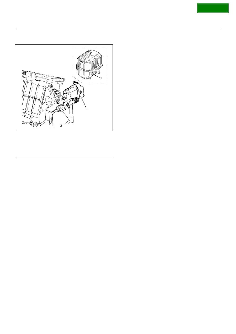
Intake Actuator
860RX018
EndOFCallout
Removal
1. Disconnect the battery ground cable.
2. Remove the blower assembly.
• Refer to Blower Assembly section.
3. Disconnect the intake actuator connector.
4. Remove the intake actuator.
Installation
To install, follow the remove step in the reverse order.
Legend
(1) Evaporator Assembly
(2) Intake Actuator
(3) Intake Actuator Connector