Content .. 1253 1254 1255 1256 ..
Opel Frontera UE. Manual - part 1255
HEATING, VENTILATION AND AIR CONDITIONING (HVAC)
1A–141
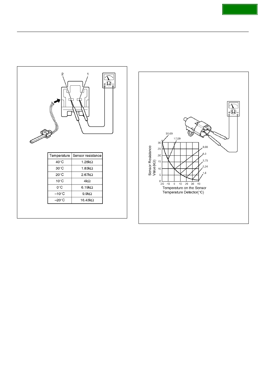
Duct Sensor
1. Disconnect the duct sensor connector (C–64).
2. Measure resistance between the duct sensor side
terminal No.C64–1 and No.C64–2.
C01R100006
Ambient Sensor
1. Disconnect the connector (C–8) on the ambient
sensor.
2. Measure resistance between the ambient sensor
side terminals.
C01RX012