Opel Frontera UE. Manual - part 1253


  Index      Opel     Opel Frontera UE - service repair manual 1999-2001 year


Search            


Content   ..  1251  1252  1253  1254   ..


Opel Frontera UE. Manual - part 1253


HEATING, VENTILATION AND AIR CONDITIONING (HVAC)

1A–133

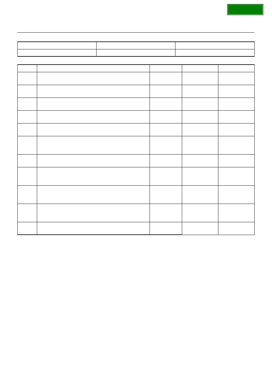
Chart A: Heating Start Timing Control Failure

CAUTION:  There are conditions which air
conditioner system does not operate except trouble
as follows.

1. The throttle is griater than 90%.

2. The ignition voltage is below 10.5 volts.

3. The engine speed greater than 4500 RPM for 5

seconds or 5400 RPM.

4. The engine coolant temperature (ECT) is greater

than 125

°°°°

C (257

°°°°

F).

5. The intake air temperature (IAT) is less than 5

°°°°

C

(41

°°°°

F).

6. The power steering pressure switch signals a high

pressure condition.

Condition

Possible cause

Correction

Heating start timing control failure

Refer to Chart A

Step

Action

Value(s)

Yes

No

Is the fuse No.F–5 normal?

Go to Step 2

Replace the 

fuse

Is the relay No.X–1 normal?

Go to Step 3

Replace the 

relay

Is the thermo unit No.E–23 normal?

Go to Step 4

Replace the 

thermo unit

Is the resistor No.C–73 normal?

Go to Step 5

Replace the 

resistor

Is there continuity between the harness side
connector terminal No.C73–1 and No.E23–1?

Go to Step 7

Go to Step 6

Repair an open circuit between terminal No.C73–1
and No.E23–1.
Is the action complete?

Go to Step 5

Is there continuity between the harness side
connector terminal No.C73–3 and No.I44–4?

Go to Step 9

Go to Step 8

Repair an open circuit between terminal No.C73–3
and No.I44–4.
Is the action complete?

Go to Step 7

Turn on the ignition switch (the engine is run).
Is the battery voltage applied between the harness
side connector terminal No.C73–2 and ground?

Go to Step 11

Go to Step 10

10 

Repair an open circuit between terminal No.C73–2
and No.F–5 fuse.
Is the action complete?

Go to Step 9

11 

Replace the auto air conditioner control unit.
Is the action complete?

Verify repair

SECTION

1A–134

HEATING, VENTILATION AND AIR CONDITIONING (HVAC)

Inspection of the Magnetic Clutch System

6VD1 Engine

D08R100231

SECTION

HEATING, VENTILATION AND AIR CONDITIONING (HVAC)

1A–135

Chart A: Magnetic Clutch Does Not work

Condition

Possible cause

Correction

Magnetic clutch does not work

Refer to Chart A

Step

Action

Value(s)

Yes

No

Is the fuse No.F–5 normal?

Go to Step 2

Replace the 

fuse

Is the relay No.X–2 (compressor relay) No.X–8 (A/C
thermo relay) and No.X–1 (heater relay) normal?

Go to Step 3

Replace the 

relay

3

Is the pressure switch normal?

Go to Step 4

Replace the 

pressure switch

4

Is the duct sensor normal?

Go to Step 5

Replace the 

duct sensor

1. Turn the ignition switch on. (the engine is run.) 

2. Turn the air conditioner switch on.

Is the battery voltage applied between the harness
side connector terminal No.E3–1 and the ground?

Go to Step 6

Go to Step 7

Repair or replace the magnetic clutch.
Is the action complete?

Verify repair

Is there continuity between the harness side
connector terminal No.X2–1 and No.E3–1?

Go to Step 9

Go to Step 8

Repair an open circuit between terminal No.X2–1 and
No.E3–1.
Is the action complete?

Go to Step 7

Is the battery voltage applied between the harness
side connector terminal No.X2–5 and ground, No.X2–
2 and ground?

Go to Step 11

Go to Step 10

10 

Repair an open circuit between terminal No.X2–5 and
fuse No.F–5, No.X2–2 and fuse No.F–5.
Is the action complete?

Go to Step 9

11 

Is the battery voltage applied between the harness
side connector terminal No.C11–1 and ground?

Go to Step 13

Go to Step 12

12 

Repair an open circuit between terminal No.C11–1
and fuse No.F–5.
Is the action complete?

Go to Step 11

13 

Is the battery voltage applied between the harness
side connector terminal No.X8–3 and ground, No.X8–
1 and ground?

Go to Step 15

Go to Step 14

14 

Repair an open circuit between terminal No.X8–3 and
No.C11–2, No.X8–1 and fuse No.F–5.
Is the action complete?

Go to Step 13

15 

Is the battery voltage applied between the harness
side connector terminal No.I20–14 and ground?

Go to Step 17

Go to Step 16

16 

Repair an open circuit between terminal No.X8–5 and
I20–14.
Is the action complete?

Go to Step 15

17 

Is there continuity between the harness side
connector terminal No.C64–1 and No.I44–20?

Go to Step 19

Go to Step 18

18 

Repair an open circuit between terminal No.C64–1
and No.I44–20.
Is the action complete?

Go to Step 17

SECTION

1A–136

HEATING, VENTILATION AND AIR CONDITIONING (HVAC)

Chart A: Magnetic Clutch Does Not work (Cont’d)

CAUTION:  There are conditions which air
conditioner system does not operate except trouble
as follows.

1. The throttle is griater than 90%.

2. The ignition voltage is below 10.5 volts.

3. The engine speed greater than 4500 RPM for 5

seconds or 5400 RPM.

4. The engine coolant temperature (ECT) is greater

than 125

°°°°

C (257

°°°°

F).

5. The intake air temperature (IAT) is less than 5

°°°°

C

(41

°°°°

F).

6. The power steering pressure switch signals a high

pressure condition.

Step

Action

Value(s)

Yes

No

19 

Is there continuity between the harness side
connector terminal No.C64–2 and No.I44–11?

Go to Step 21

Go to Step 20

20 

Repair an open circuit between terminal No.C64–2
and No.I44–11.
Is the action complete?

Go to Step 19

21 

Is there continuity between the harness side
connector terminal No.X8–2 and PCM (F45)?

Go to Step 23

Go to Step 22

22 

Repair an open circuit between terminal No.X8–2 and
PCM (F45)?
Is the action complete?

Go to Step 21

23 

Is there continuity between the harness side
connector terminal No.X2–4 and PCM (F4)?

Go to Step 25

Go to Step 24

24 

Repair an open circuit between terminal No.X2–4 and
PCM (F4).
Is the action complete?

Go to Step 23

25 

1. Connect the connector of PCM.

2. Connect the harness side connector terminal

I20–14 to the ground.

Does the magnetic clutch work?

Replace the 

auto air 

conditioner 
control unit

Refer to 

Powertrain 

Control Modul 

in ENGINE 

DRIVEABILITY 

AND 

EMISSIONS 

section

SECTION


Content   ..  1251  1252  1253  1254   ..