Content .. 1235 1236 1237 1238 ..
Opel Frontera UE. Manual - part 1237
HEATING, VENTILATION AND AIR CONDITIONING (HVAC)
1A–69
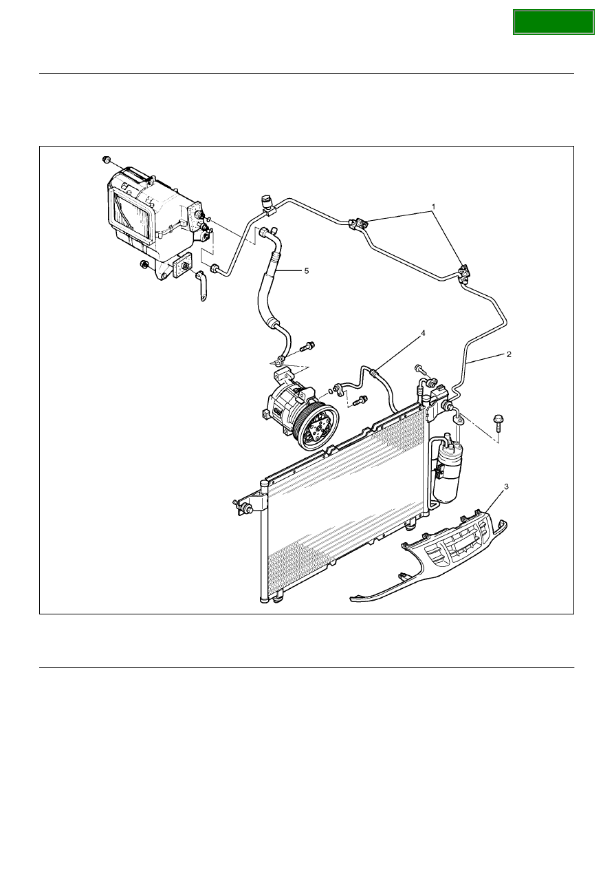
Refrigerant Line
Refrigerant Line and Associated Parts
852R100008
EndOFCallout
Removal
1. Disconnect the battery ground cable.
2. Discharge and recover refrigerant.
• Refer to Refrigerant Recovery in this section.
3. Remove radiator grille.
4. Remove clip and clamp.
5. Disconnect liquid line (High-pressure pipe).
6. Disconnect suction line (Low-pressure pipe) using a
back-up wrench.
7. Disconnect suction line (Low-pressure hose) using
a back-up wrench.
8. Disconnect discharge line (High-pressure hose)
using a back-up wrench.
• Use a backup wrench when disconnecting and
reconnecting the refrigerant lines.
• When removing the refrigerant line connecting
part, the connecting part should immediately be
Legend
(1) Clip and Clamp
(2) Liquid Line (High-Pressure Pipe)
(3) Radiator Grille
(4) Discharge Line (High-Pressure Hose)
(5) Suction Line (Low-Pressure Pipe)