Opel Frontera UE. Manual - part 1235


  Index      Opel     Opel Frontera UE - service repair manual 1999-2001 year


Search            


Content   ..  1233  1234  1235  1236   ..


Opel Frontera UE. Manual - part 1235


HEATING, VENTILATION AND AIR CONDITIONING (HVAC)

1A–61

Torque: 15 N•m (1.5kg•m/11 lb ft)

• Tighten the outlet line connector fixing bolt to the

specified torque.

Torque: 6 N•m (0.6kg•m/52 lb in)

• O-rings cannot be reused. Always replace with

new ones.

• Be sure to apply new compressor oil to the

O-rings when connecting the refrigerant line.

3. Connect pressure switch & condenser fan motor

connector.

4. Install engine hood lock.

5. Install engine hood front end stay.

6. Install radiator grille.
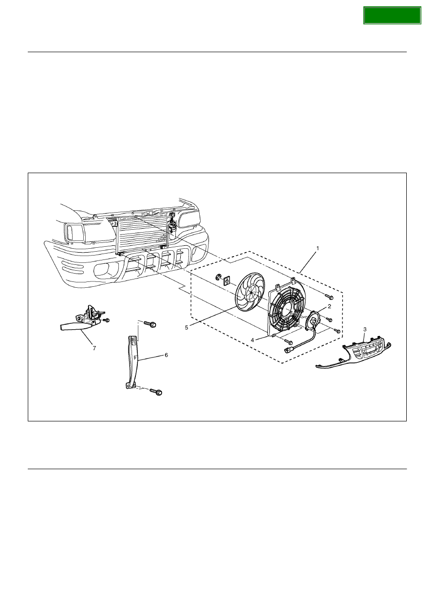
Condenser Fan Motor

Condenser Fan Motor and Associated Parts

875R100005

EndOFCallout

Removal

1. Disconnect the battery ground cable.

2. Discharge and recover refrigerant.

• Refer to Refrigerant Recovery in this section.

3. Remove radiator grille.

4. Remove engine hood front end stay.

5. Remove engine hood lock.

6. Remove condenser fan assembly.

• Disconnect the fan motor connector and remove

the 3 fixing bolts.

7. Remove shroud.

• Remove the 3 fixing nuts.

• Loosen the condenser fixing nut and disconnect

the fan motor connector from bracket.

8. Remove fan.

• Remove the fan fixing C-ring and plate.

9. Remove condenser fan motor.

Legend

(1) Condenser Fan Assembly
(2) Condenser Fan Motor
(3) Radiator Grille

(4) Shroud
(5) Fan
(6) Engine Hood Front End Stay
(7) Engine Hood Lock

SECTION

1A–62

HEATING, VENTILATION AND AIR CONDITIONING (HVAC)

Installation

To install, follow the removal steps in the reverse order,
noting the following point.

1. Route the fan motor harness in its previous position,

and fix it securely with clip and bracket.

SECTION

HEATING, VENTILATION AND AIR CONDITIONING (HVAC)

1A–63

Receiver / Drier

Receiver / Drier and Associated
Parts

875R100007

EndOFCallout

Removal

1. Disconnect the battery ground cable.

2. Discharge and recover refrigerant.

• Refer to Refrigerant Recovery in this section.

3. Remove radiator grille.

4. Disconnect pressure switch connector.

5. Disconnect refrigerant line.

• When removing the line connected part, the

connecting part should immediately be plugged
or capped to prevent foreign matter from being
mixed into the line.       

6. Remove receiver/drier.

• Loosen the bolt, then, using care not to touch or

bend the refrigerant line, carefully pull out the
receiver/drier.

Installation

To install, follow the removal steps in the reverse order,
noting the following points:

1. If installing a new receiver/drier, be sure to add 30cc

(1.0 fl.oz.) of new compressor oil to a new one.

2. Put the receiver/drier in the bracket and connect

with the refrigerant line.  Check that no excessive
force is imposed on the line.  Fasten the bracket bolt
to the receiver/drier.

3. Tighten the refrigerant line to the specified torque.

Torque: 6 N•m (0.6kg•m/52 lb in)

4. O-rings cannot be reused. Always replace with new

ones.

5. Be sure to apply new compressor oil to the O-rings

when connecting the refrigerant line.

Legend

(1) Pressure Switch Connector
(2) Refrigerant Line
(3) Radiator Grille
(4) Receiver / Drier

SECTION

1A–64

HEATING, VENTILATION AND AIR CONDITIONING (HVAC)

Pressure Switch

Pressure Switch and Associated
Parts

875R100008

EndOFCallout

Removal

1. Disconnect the battery ground cable.

2. Discharge and recover refrigerant.

• Refer to “Refrigerant Recovery in this section.

3. Remove radiator grille.

4. Disconnect pressure switch connector.

5. Disconnect pressure switch.

• When removing the switch connected part, the

connecting part should immediately be plugged
or capped to prevent foreign matter from being
mixed into the line.

Installation

To install, follow the removal steps in the reverse order,
noting the following point:

1. O-ring cannot be reused. Always replace with a new

one.

2. Be sure to apply new compressor oil to the O-ring

when connecting pressure switch.

3. Tighten the pressure switch to the specified torque.

Torque: 13 N•m (1.3kg•m/113 lb in)

Legend

(1) Pressure Switch Connector
(2) Pressure Switch
(3) Refrigerant Line
(4) Radiator Grille

SECTION


Content   ..  1233  1234  1235  1236   ..