Opel Frontera UE. Manual - part 1224


  Index      Opel     Opel Frontera UE - service repair manual 1999-2001 year


Search            


Content   ..  1222  1223  1224  1225   ..


Opel Frontera UE. Manual - part 1224


HEATING, VENTILATION AND AIR CONDITIONING (HVAC)

1A–17

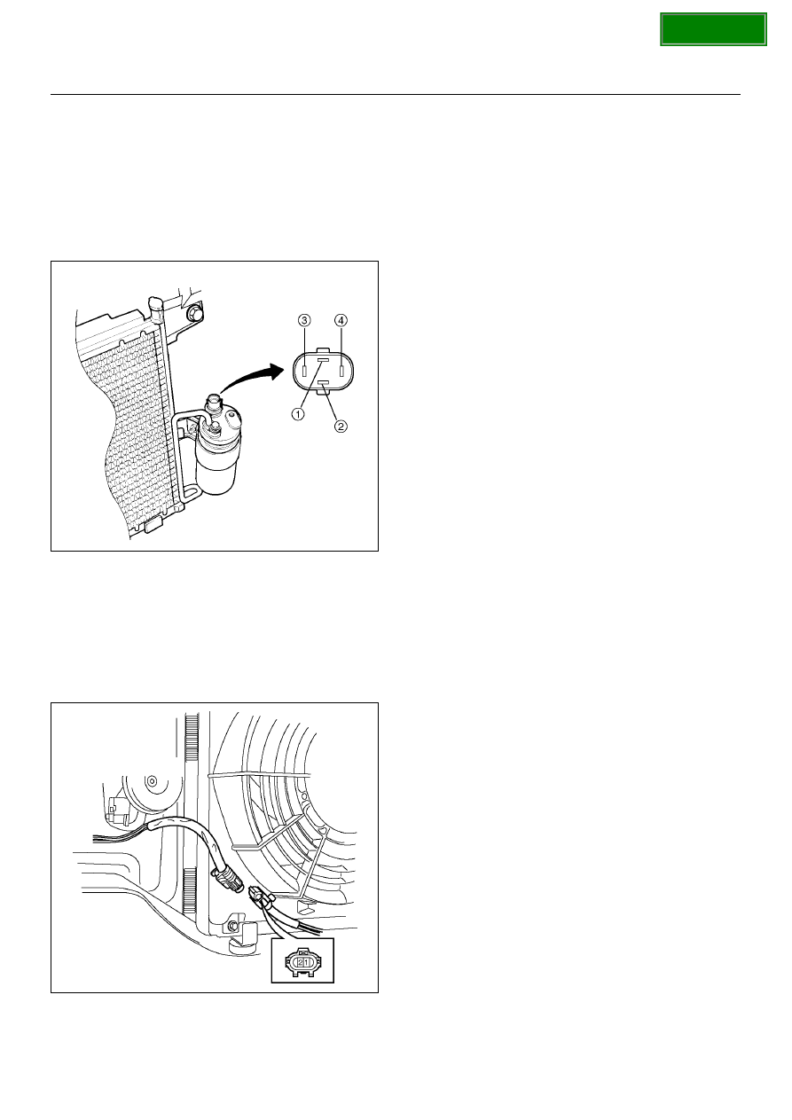
Triple Pressure Switch (V6, A/T)

1. Disconnect the connector and check for continuity

between pressure switch side connector terminals
(1) and (2).

2. Reconnect the connector to activate the A/C switch,

and check to see if there is continuity between the
chassis side connector terminals (3) and (4) and the
fan operates.

875RY00010

Condenser Fan

1. Disconnect the condenser fan connector.

2. Connect the battery positive terminal to the

condenser fan side connector terminal No.C-24-1
and negative to the No.C-24-2.

3. Check that condenser fan is rotating correctly.

875RW010

General Repair Procedure

Precautions For Replacement or Repair of
Air Conditioning Parts

There are certain procedures, practices and
precautions that should be followed when servicing air
conditioning systems:

• Keep your work area clean.

• Always wear safety goggles and protective gloves

when working on refrigerant systems.

• Beware of the danger of carbon monoxide fumes

caused by running the engine.

• Beware of discharged refrigerant in enclosed or

improperly ventilated garages.

• Always disconnect the negative battery cable and

discharge and recover the refrigerant whenever
repairing the air conditioning system.

• When discharging and recovering the refrigerant, do

not allow refrigerant to discharge too fast; it will draw
compressor oil out of the system.

• Keep moisture and contaminants out of the system.

When disconnecting or removing any lines or parts,
use plugs or caps to close the fittings immediately.   
Never remove the caps or plugs until the lines or
parts are reconnected or installed.

• When disconnecting or reconnecting the lines, use

two wrenches to support the line fitting, to prevent
from twisting or other damage.

• Always install new O-rings whenever a connection is

disassembled.

• Before connecting any hoses or lines, apply new

specified compressor oil to the O-rings.

• When removing and replacing any parts which

require discharging the refrigerant circuit, the
operations described in this section must be
performed in the following sequence:

1 Use the J-39500 (ACR

4

: HFC-134a Refrigerant

Recovery / Recycling  / Recharging / System) or
equivalent to thoroughly discharge and recover
the refrigerant.

2 Remove and replace the defective part.

3 After evacuation, charge the air conditioning

system and check for leaks.       

SECTION

1A–18

HEATING, VENTILATION AND AIR CONDITIONING (HVAC)

Fan Control Lever (Fan Switch)

1. Check for continuity between the terminals of the

fan switch.

D08RX157

EndOFCallout

Heater Relay

1. Disconnect the heater relay (X-1).

• When removing the connector for relay, unfasten

the tank lock of the connector by using a
screwdriver, then pull the relay (1) out.

825RX046

2. Check for continuity between the heater relay (X-1)

terminals.

901RX071

Legend

(1) Control Lever Connector Terminal (Control 

Lever Side)

(2) Position Switch

SECTION

HEATING, VENTILATION AND AIR CONDITIONING (HVAC)

1A–19

Heater Unit

Heater Unit and Associated Parts

840R100003

EndOFCallout

Removal

1. Disconnect the battery ground cable.

2. Drain the engine coolant.

3. Discharge and recover refrigerant (with air

conditioning).

• Refer to Refrigerant Recovery in this section.

4. Remove the Instrument panel assembly.

• Refer to Instrument Panel Assembly in Body and

Accessories section.

5. Remove instrument panel stay.

6. Remove center ventilation duct and side defroster.

7. Disconnect resistor connector.

8. Remove evaporator assembly.

• Refer to Evaporator Assembly in this section.

9. Remove ventilation lower duct.

10. Remove rear heater duct.

• Remove foot rest, carpet and 3 clips.

11. Remove heater unit assembly.

• Disconnect heater hoses at heater unit.

Legend

(1) Instrument Panel Assembly
(2) Resistor Connector
(3) Heater Hose
(4) Heater Unit Assembly

(5) Evaporator Assembly
(6) Rear Heater Duct
(7) Ventilation Lower Duct
(8) Instrument Panel Stay
(9) Center Ventilation Duct and Side Defroster

SECTION

1A–20

HEATING, VENTILATION AND AIR CONDITIONING (HVAC)

Installation

To install, follow the removal steps in the reverse order,
noting the following points:

1. When handling the PCM and the control unit, be

careful not to make any improper connection of the
connectors.

2. Adjust the control cables.

• Refer to Control Lever Assembly in this section.

3. When installing the heater unit, defroster nozzle and

center vent duct, be sure that the proper seal is
made, without any gap between them.

4. After putting engine coolant in remove the air well

and confirm the quantity of coolant.

Heater Core and / or Mode Door

Disassembled View

860RX002

EndOFCallout

Removal

1. Disconnect the battery ground cable.

2. Drain the engine coolant.

Legend

(1) Heater Unit
(2) Case (Temperature Control)
(3) Heater Core

(4) Case (Mode Control)
(5) Duct
(6) Mode Door

SECTION


Content   ..  1222  1223  1224  1225   ..