Content .. 1200 1201 1202 1203 ..
Opel Frontera UE. Manual - part 1202
9J1–16
RESTRAINT CONTROL SYSTEM
DTC 15 Passenger Deployment Loop Resistance High
D09RX002
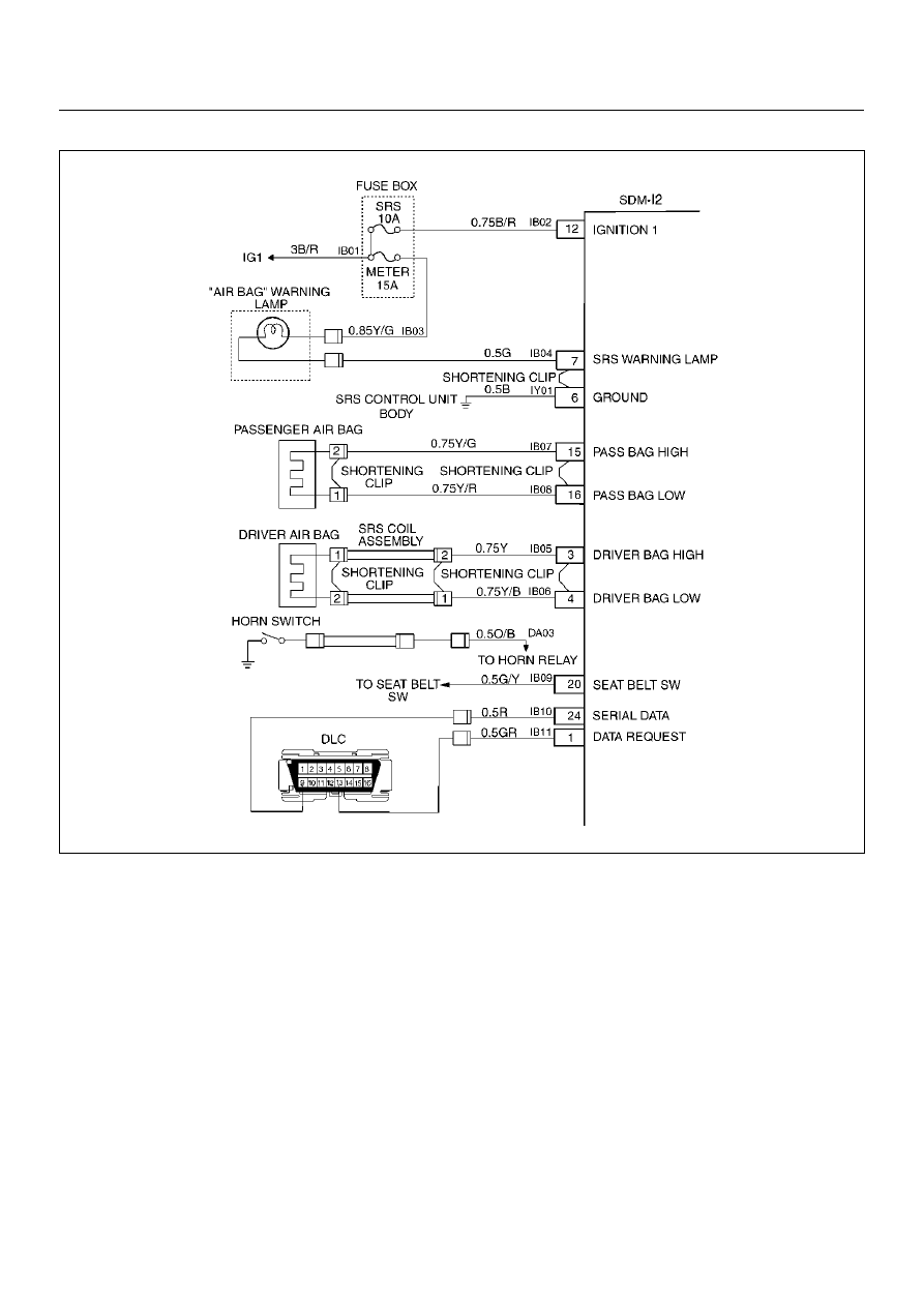
Circuit Description:
When the ignition switch is turned “ON", the Sensing
and Diagnostic Module (SDM) will perform tests to
diagnose critical malfunctions within itself. Upon
passing these tests “ignition 1", and deployment loop
voltages are measured to ensure they are within their
respective normal voltage ranges. The SDM then
proceeds with the “Resistance Measurement Test".
“Passenger Bag Low" terminal “16" is grounded
through a resister and the passenger current source
connected to “Passenger Bag High" terminal “15" allows
a known amount of current to flow. By monitoring the
voltage difference between “Passenger Bag High" and
“Passenger Bag Low" the SDM calculates the
combined resistance of the passenger air bag
assembly, harness wiring Circuits(CKTs) IB07–
YELLOW/GREEN and IB08–YELLOW/RED connector
terminal contact.
DTC Will Set When:
The combined resistance of the passenger air bag
assembly, harness wiring CKTs IB07–YELLOW/GREEN
and IB08–YELLOW/RED, and connector terminal
contact is above a specified value. This test is run once
each ignition cycle during the “Resistance
Measurement Test" when:
1. No “higher priority faults" are detected during “Turn–
ON."
2. “Ignition 1" voltage is in the specified value.
Action Taken:
SDM turns “ON" the “AIR BAG" warning lamp and sets
a diagnostic trouble code.