Opel Frontera UE. Manual - part 1199


  Index      Opel     Opel Frontera UE - service repair manual 1999-2001 year


Search            


Content   ..  1197  1198  1199  1200   ..


Opel Frontera UE. Manual - part 1199


9J1–4

RESTRAINT CONTROL SYSTEM

Parts For Electrical Circuit
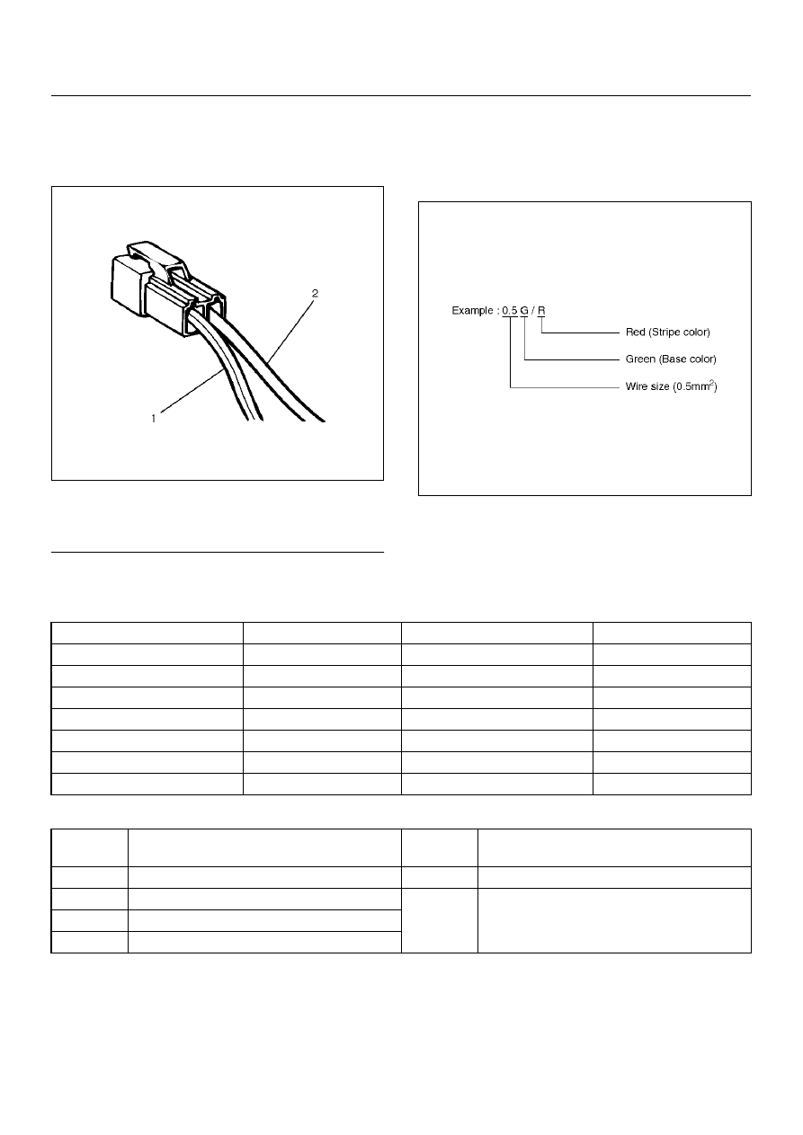
Wiring

Wire Color

D08RX174

Legend

EndOFCallout

All wires have color-coded insulation.
Wires belonging to a system’s main harness wil have a 
single color. Wires belonging to a system’s sub-circuits 
will have a colored stripe. Striped wires use the following 
code to show wire size and colors.

D08RX175

Abbreviations are used to indicate wire color within a 
circuit diagram.
Refer to the following table.

Wire Color Coding

Distinction of Circuit by Wire Base Color

(1) Colored Stripe
(2) Single Color

Color-coding

Meaning

Color-coding

Meaning

B

Black

BR

Brown

W

White

LG

Light green

R

Red

GR

Grey

G

Green

P

Pink

Y

Yellow

LB

Light blue

L

Blue

V

Violet

O

Orange

Base 
color

Circuits

Base 

color

Circuits

B

Starter circuit and grounding circuit

Y

Instrument circuit

W

Charging circuit

L, O, BR, 

LG, GR, P, 

SB, V

Other circuit

R

Lighting circuit

G

Signal circuits

RESTRAINT CONTROL SYSTEM

9J1–5

System Schematic

D09RX002

SRS Diagnostic System Check

The diagnostic procedures used in this section are 
designed to find and repair Supplemental Restraint 
System (SRS) malfunctions.   To get the best results, it 
is important to use the diagnostic charts and follow the 
sequence listed below:

A

Perform the “SRS Diagnostic System Check."
The “SRS Diagnostic System Check" must be the 
starting point of any SRS diagnostics.   The “SRS 
Diagnostic System Check" checks for proper “AIR 
BAG" warning lamp operation,  the ability of the 
Sensing and Diagnostic Module (SDM) to 
communicate through the “Serial Data" line and 
whether SRS diagnostic trouble codes exist.

B

Refer to the proper diagnostic chart as directed by 
the “SRS Diagnostic System Check."
The “SRS Diagnostic System Check" will lead you 

to the correct chart to diagnose any SRS 
malfunctions.   Bypassing these procedures may 
result in extended diagnostic time, incorrect 
diagnosis and incorrect parts replacement.

C

Repeat the “SRS Diagnostic System Check" after 
any repair or diagnostic procedures have been 
performed.
Performing the “SRS Diagnostic System Check" 
after all repair or diagnostic procedures will ensure 
that the repair  has been made correctly and that no 
other malfunctions exist

Circuit Description

When the ignition switch is first turned “ON", “ignition 1" 
voltage is applied from the “SRS" fuse to the SDM at the 
“ignition 1" input terminals “12".  The SDM responds by 
flashing the “AIR BAG" warning lamp seven  times while 
performing tests on the SRS.

9J1–6

RESTRAINT CONTROL SYSTEM

Notes On System Check Chart:

Number(s) below refer to step number(s) on the 
“Supplemental Restraint System Diagnostic System 
Check" chart.
1. The “AIR BAG" warning lamp should flash seven 

times after ignition is first turned “ON."

2. After the “AIR BAG" warning lamp flashes seven 

times, it should turn “OFF."

3. Improper operation of the “AIR BAG" warning lamp is 

indicated.  This test differentiates a warning lamp 
stays “ON" condition from a warning lamp does not 
come “ON" condition. 

4. This test checks for the proper operation of the “Serial 

Data" line.  This test will also determine whether 
history diagnostic trouble codes are stored and, if so, 
identify them.

5. This test checks for proper operation of the “Serial 

Data" line.  This test will also identify the stored 
diagnostic trouble codes and whether they are 
current or history.

Diagnostic Aids:

The order in which diagnostic trouble codes are 
diagnosed is very important.  Failure to diagnose the 
diagnostic trouble codes in the order specified may 
result in extended diagnostic time, incorrect diagnosis 
and incorrect parts Replacement.

RESTRAINT CONTROL SYSTEM

9J1–7

SRS Diagnostic System Check

Step

Action

Yes

No

1

Note the “AIR BAG" warning lamp when ignition switch is turned 
“ON."
Does the “AIR BAG" warning lamp flash seven (7) times?

Go to Step 2 

Go to Step 3

2

Note the “AIR BAG" warning lamp after it flashed 7 times.
Does the “AIR BAG" warning lamp go “OFF"?

Go to Step 4

Go to Step 5

3

Note the “AIR BAG" warning lamp when ignition switch is turned 
“ON."
Does the “AIR BAG" warning lamp come “ON" steady?

Go to Chart B.

Go to Chart C.

4

1. Ignition switch “OFF."

2. Connect a scan tool to data link connector.

3. Follow direction given in the scan tool instruction manual.

4. Ignition switch “ON."

5. Request the SRS diagnostic trouble code display recode all 

history diagnostic trouble code(s) specify as such, on repair 
order.

Is diagnostic trouble code(s) displayed?

Ignition switch 

“OFF."

When DTC 71 

is set, go to 

DTC 71 chart.

For all other 

history codes 

refer to 

“Diagnostics 

Aids" for that 

specific DTC.

A history DTC 

indicates the 

malfunction has 

been repaired 

or is 

intermittent.

SRS is 

functional and 

free of 

malfunctions, 

no further 

diagnosis is 

required.

If scan tool 

indicates “No 

Data Received," 

refer to chassis 

electrical 

section.


Content   ..  1197  1198  1199  1200   ..