Opel Frontera UE. Manual - part 1197


  Index      Opel     Opel Frontera UE - service repair manual 1999-2001 year


Search            


Content   ..  1195  1196  1197  1198   ..


Opel Frontera UE. Manual - part 1197


SUPPLEMENTAL RESTRAINT SYSTEM

9J–47

Installation

1. Install the 2nd shaft (14) to the column shaft 

assembly (13).

2. Install the steering column assembly (13).

3. Tighten the steering column fixing bolts (dash panel 

side) to the specified torque.

Torque: 20 N·m (2.0 kg·m/15 lbft)

4. Tighten the steering column fixing nuts (Cross 

beam) to the specified torque. 

Torque: 17 N·m (1.7 kg·m/13 lbft)

5. Tighten the universal joint to the specified  torque. 

Torque: 31 N·m (3.2 kg·m/23 lbft)

6. Install steering lock cylinder assembly (11).

7. Connect shift lock cable.

8. Install cushion rubber.

9. Install snap ring.

10. Install the combination switch assembly with 

Supplemental Restraint System (SRS) coil (9).

11. Connect the wiring harness connector (10) located 

on the base of steering column.

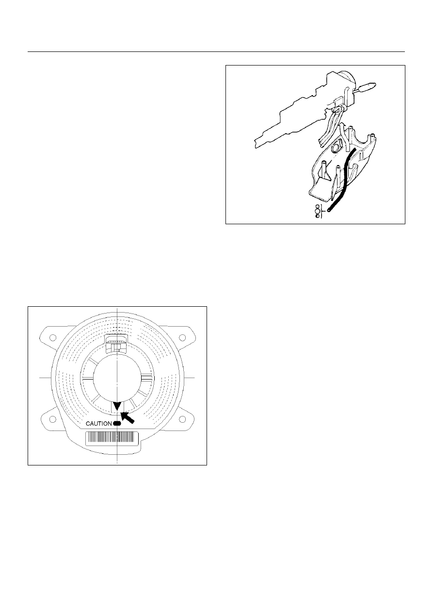
12. Turn the SRS coil clockwise to full, return about 3 

turns and align the neutral mark.

825RX032

CAUTION:  When turning the SRS coil clockwise to 
full, stop turning if resistance is felt. Further forced 
turning may damage the cable in the SRS coil.

13. Install steering column cover (1).

825RS048

CAUTION:  When installing the steering column 
cover, be sure to wire (through each harness) as 
illustrated so that the harnesses starter switch, 
combination switch and SRS coil may not catch 
wiring.

14. Install the steering wheel (2) and align the setting 

marks (6).

15. Tighten the steering wheel fixing nut (3) to the 

specified torque.

Torque: 34 N·m (3.5 kg·m/25 lbft)

16. Connect horn lead (8).

17. Connect air Bag wiring harness connector (7).

NOTE:  Pass the lead wire through the tabs on the 
plastic cover (wire protector) of air bag to prevent lead 
wire from being pinched.

9J–48

SUPPLEMENTAL RESTRAINT SYSTEM

18. Install air bag into steering wheel and tighten bolts 

(5) to specified sequence as shown in figure.

Torque: 8.8 N·m (9.0 kg·m/78 lbin)

CAUTION:  Never use the air bag assembly from 
another vehicle.
 Use only the air bag assembly for UE.

431RX012

19. Enable the Supplemental Restraint System (SRS) 

(Refer to “Enabling The SRS" in this section.)

SUPPLEMENTAL RESTRAINT SYSTEM

9J–49

Passenger Air Bag Assembly

Service Precaution

WARNING:  SAFETY PRECAUTIONS MUST BE 
FOLLOWED WHEN HANDLING A DEPLOYED AIR 
BAG ASSEMBLY. AFTER DEPLOYMENT, THE AIR 
BAG ASSEMBLY SURFACE MAY CONTAIN A SMALL 
AMOUNT OF SODIUM HYDROXIDE, A BY-PRODUCT 
OF THE DEPLOYMENT REACTION, THAT IS 
IRRITATING TO THE SKIN AND EYES. MOST OF THE 
POWDER ON THE AIR BAG ASSEMBLY IS 
HARMLESS. AS A PRECAUTION, WEAR GLOVES 
AND SAFETY GLASSES WHEN HANDLING A 
DEPLOYED AIR BAG ASSEMBLY, AND WASH YOUR 
HANDS WITH MILD SOAP AND WATER 
AFTERWARDS.

WARNING:  WHEN CARRYING A LIVE AIR BAG 
ASSEMBLY, MAKE SURE THE BAG AND TRIM 
COVER ARE POINTED AWAY FROM YOU. NEVER 
CARRY AIR BAG ASSEMBLY BY THE WIRES OR 
CONNECTOR ON THE UNDERSIDE OF MODULE. IN 
THE CASE OF AN ACCIDENTAL DEPLOYMENT, THE 
BAG WILL THEN DEPLOY WITH MINIMAL CHANCE 
OF INJURY. WHEN PLACING A LIVE AIR BAG 
ASSEMBLY ON A BENCH OR OTHER SURFACE, 
ALWAYS FACE BAG AND TRIM COVER UP, AWAY 
FROM THE SURFACE. NEVER REST A STEERING 
COLUMN ASSEMBLY ON THE STEERING WHEEL 
WITH THE AIR BAG ASSEMBLY FACE DOWN AND 
COLUMN VERTICAL. THIS IS NECESSARY SO THAT 
A FREE SPACE IS PROVIDED TO ALLOW THE AIR 
BAG ASSEMBLY TO EXPAND IN THE UNLIKELY 
EVENT OF ACCIDENTAL DEPLOYMENT. 
OTHERWISE, PERSONAL INJURY COULD RESULT.

In the event deployment has occurred, inspect coil 
assembly wire for any signs of scorching, melting or any 
other damage due to excessive heat. If the coil has 
been damaged, replace it.

Removal

1. Disable the SRS. (Refer to “Disabling the SRS" in 

this section.)

2. Remove glove box assembly.

3. Disconnect passenger air bag assembly harness 

connector.

4. Remove air bag assembly fixing bolts and nuts.

5. Remove reinforcement.

6. Remove passenger air bag assembly from glove 

box opening of instrument panel.

827RX051

Installation

1. Install passenger air bag assembly from glove box 

opening of instrument panel.

2. Install reinforcement from glove box opening of 

instrument panel.

3. Install air bag assembly fixing nuts and bolts, and 

tighten to specified torque.

Torque: 7.8 N·m (69 lbin)

4. Connect air bag assembly harness connector.

5. Install glove box assembly.

6. Enable the SRS (Refer to “Enabling the SRS" in this 

section.)

827RW062

9J–50

SUPPLEMENTAL RESTRAINT SYSTEM

Main Data and Specifications

Fastener Tightening Specification

Application

N·m

kg·m

Ib Ft

Ib In

SDM

10

1.0

87

Driver air bag fixing bolt

8.8

0.9

78

Steering wheel fixing bolt

34

3.5

25

Steering column (dash panel side fixing bolts)

20

2.0

15

Steering column (Cross beam side fixing nuts)

17

1.7

13

Steering column (Universal joint fixing bolt)

31

3.2

23

Passenger Air Bag fixing bolts and nuts

6

0.6

52


Content   ..  1195  1196  1197  1198   ..