Opel Frontera UE. Manual - part 1152


  Index      Opel     Opel Frontera UE - service repair manual 1999-2001 year


Search            


Content   ..  1150  1151  1152  1153   ..


Opel Frontera UE. Manual - part 1152


BODY STRUCTURE

8F–39

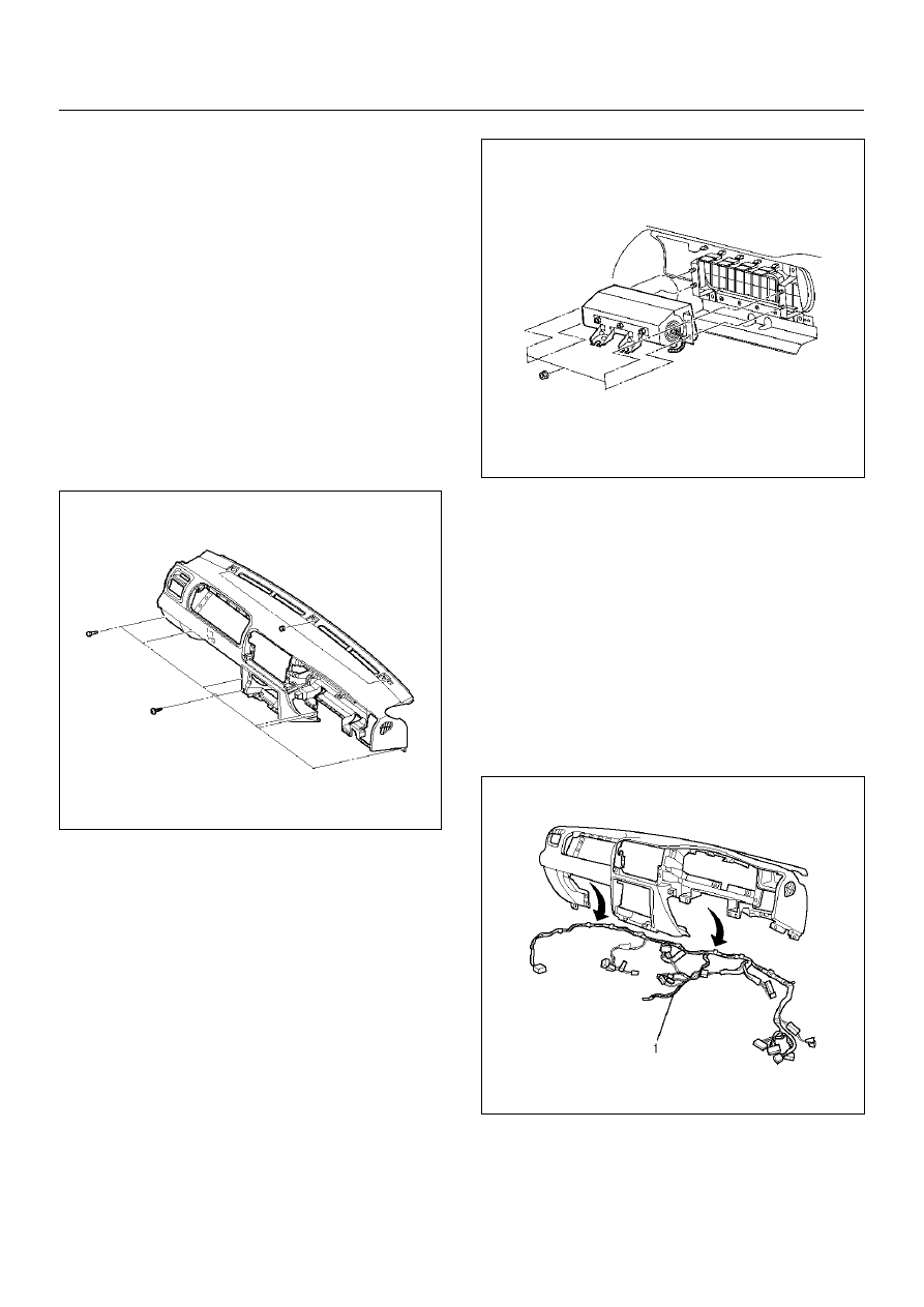
12. Remove the Instrument panel assembly.

CAUTION:  For precautions on installation or 
removal of SRS – air bag system, refer to 
Supplemental  Restraint System (SRS) – AIR BAG in 
Restraint section.

• Disconnect the instrument harness connectors 

(six connectors on the driver's side, three 
connectors on the passenger side and two 
connectors on the center side).

• Disconnect radio antenna cable plug and the 

ground cable fixing bolts from dash side panel.

• Remove the two fixing bolts of passenger air bag 

assembly and disconnect the connector.

• Remove the two fixing screws from fuse box.

• After pry the three hole cover from the surface of 

instrument panel, remove the three nuts.

• Remove the six bolts and one screw.

740RX070

13. Remove the passenger air bag.

• Remove the four fixing nuts.

CAUTION:  For precautions on installation or 
removal of SRS – air bag system, refer to 
Supplemental  Restraint System in Restraint 
section.

827RY00004

14. Remove the vent duct assembly.

• Remove the five fixing screws.

15. Remove the passenger lower bracket.

• Remove the three screws.

16. Remove the glove box side reinforcement.

17. Remove the instrument upper reinforcement.

• Remove the nine screws.

18. Remove the instrument panel center reinforcement.

• Remove the six screws.

19. Remove the instrument panel harness assembly 

(1).

• Remove the clips.

740RX069

20. Remove the instrument panel stays.

• Remove the two fixing nuts and two fixing bolts 

for each bracket.

8F–40

BODY STRUCTURE

21. Remove the cross beam.

• Remove the five fixing nuts, two fixing bolts 

(upper) and six fixing bolts (lower).

840RW025

Installation

To install, follow the removal steps in the reverse order, 
noting the following point.

1. Adjust the control cable.

• Refer to Control Lever Assembly in Heating, 

Ventilation and Air Conditioning (HVAC) section.

BODY STRUCTURE

8F–41

Front Door Assembly

Parts Location

630RW044

Legend

EndOFCallout

Removal

1. Disconnect the battery ground cable.

2. Apply a setting mark on the body side hinge.

3. Remove the door check arm pin.

630RW001

(1) Front Door Assembly
(2) Lower Hinge Bolt
(3) Door Harness Connection

(4) Door Check Arm Pin
(5) Upper Hinge Bolt

8F–42

BODY STRUCTURE

4. Remove the upper and lower hinge bolts.

• Position a wood block under the door for 

protection and support the door assembly with 
hands during removal or installation.

635RW003

5. Remove the door harness connection.

• Pull the door harness grommet out in order to 

disconnect the harness connection.

630RW004

6. Remove the front door assembly.

Installation

To install, follow the removal steps in the reverse order, 
noting the following points:

1. Align the door fitting to the body.

• Check the fender and front door (1).

Clearance: 5.0 mm (0.196 in)

Height (step): Flush

• Check the front door and rear door (2).

Clearance: 6.0 mm (0.23 in)

Height (step): Flush

• Check the rear door and body (3) (4).

Clearance: 5.0 mm (0.196 in)

Height (step): Flush

Adjust clearance with door hinges.
Adjust height (step) by tapping on the fender 
lightly with a rubber hammer.

610RY00016

2. Tighten the door hinge bolts to the specified torque.

Torque : 34 N·m (3.5 kg·m/25 lb ft)


Content   ..  1150  1151  1152  1153   ..