Content .. 1107 1108 1109 1110 ..
Opel Frontera UE. Manual - part 1109
8D–147
WIRING SYSTEM
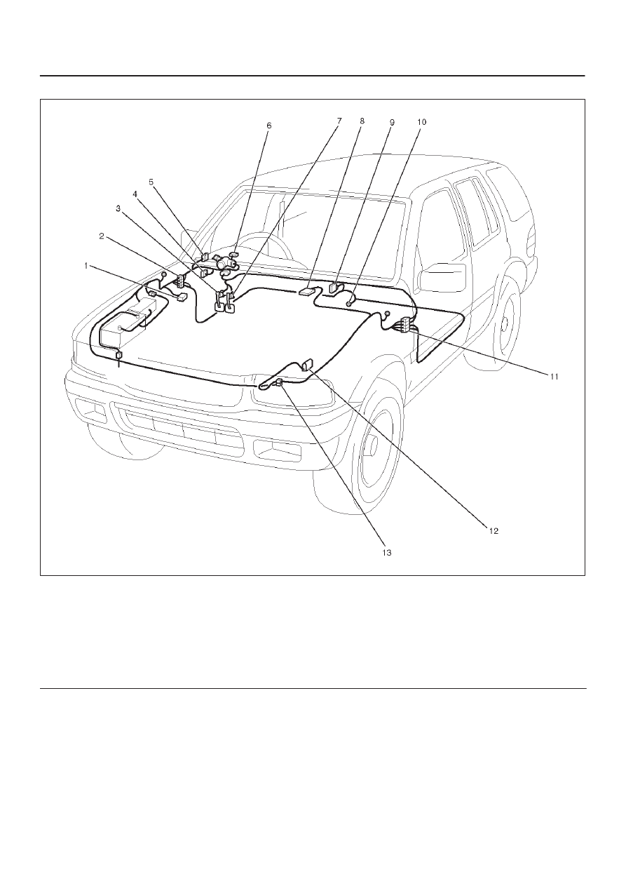
Parts Location
D08RX156
Legend
(1) C–26
(2) H–12, H–13, H–19, H–32
(3) Stoplight Switch (I–18)
(4) Relay & Fuse Box
(5) I–6
(6) I–9
(7) Clutch Switch (I–14)
(8) PCM
(9) Cruise Control Unit (B–18)
(10) B–8
(11) H–15
(12) Mode Switch (M–16)
(13) H–10, H–11