Content .. 1035 1036 1037 1038 ..
Opel Frontera UE. Manual - part 1037
TRANSMISSION CONTROL SYSTEM (4L30–E)
7A1–73
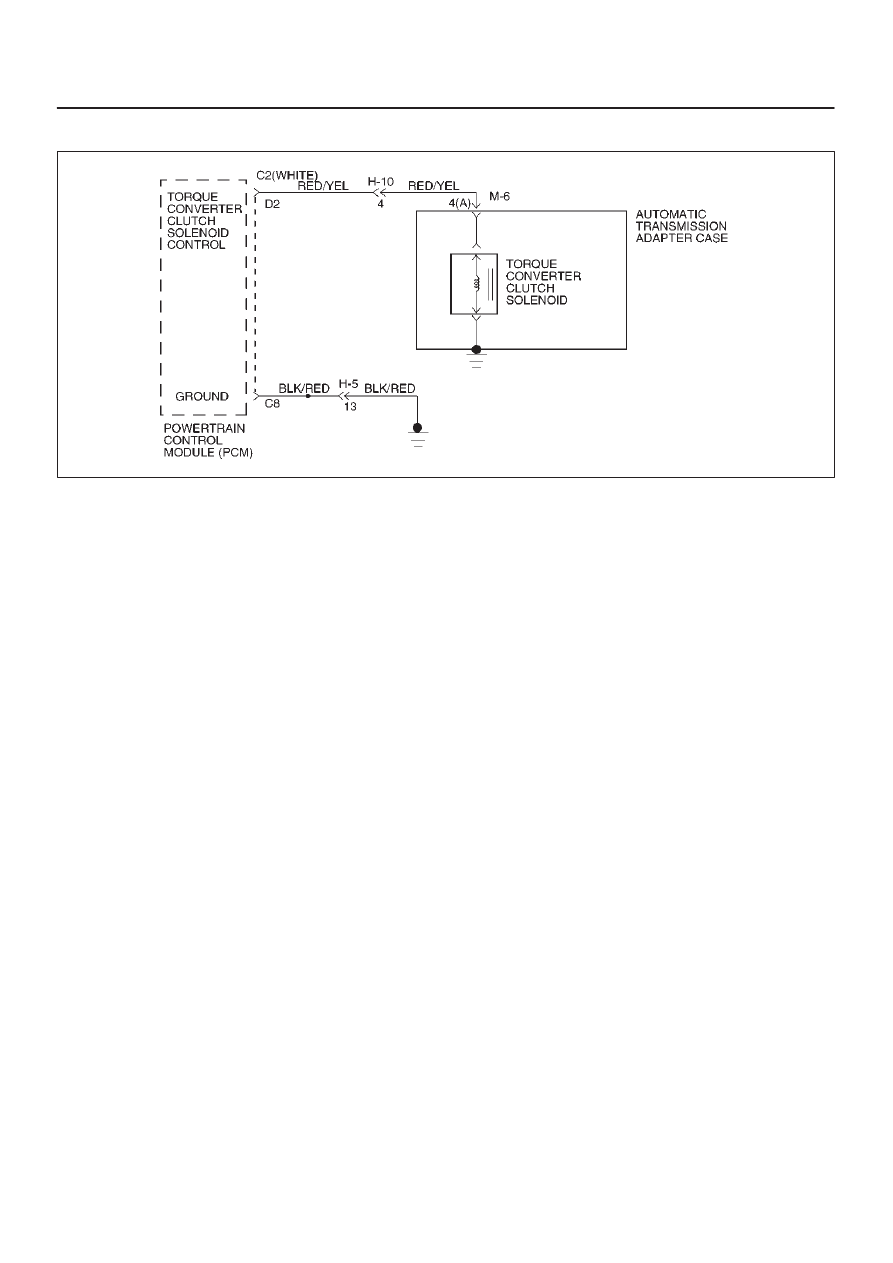
DTC P1860/Flashing Code 89 TCC Solenoid Electrical
D07RW016
Circuit Description
The PCM allows current to flow through the solenoid coil.
This current flow through the solenoid coil creates a
magnetic field that magnetizes the solid core. The
magnetized core attracts the check ball to seat against
spring pressure. This blocks the exhaust for the TCC
signal fluid and allows 2–3 drive fluid to feed to TCC signal
circuit. The TCC signal fluid pressure acts on the TCC
regulator valve to regulate line pressure and to apply fluid
pressure to the torque converter clutch shift valve. When
the TCC shift valve is in the apply position, regulated
apply fluid pressure is directed through the TCC valve to
apply the torque converter clutch. The TCC solenoid is
used in conjunction with the TCC solenoid to regulate fluid
to the torque converter. The TCC solenoid is attached to
the valve body within the transmission.
This DTC detects a continuous open or short to ground or
ignition in the TCC circuit or the TCC solenoid. This is a
type “D” DTC.
Conditions For Setting The DTC
D
Battery voltage is between 10 and 16 volts.
D
No shift solenoid A DTCs P0753.
D
No shift solenoid B DTCs P0758.
D
Ignition “on”. Engine “run”.
D
The PCM commands the solenoid “on” and the
voltage remains low (zero volts).
D
The PCM commands the solenoid “off” and the
voltage remains high (B+).
D
All conditions met for 0.25 seconds.
Action Taken When The DTC Sets
D
Inhibit TCC engagement.
D
The PCM will not illuminate the CHECK TRANS
Lamp.
Conditions For Clearing The DTC
D
The DTC can be cleared from the PCM history by
using a scan tool.
D
The DTC will be cleared from history when the vehicle
has achieved 40 warmup cycles without a failure
reported.
D
The PCM will cancel the DTC default actions when
the fault no longer exists and the ignition is cycled “off”
long enough to power down the PCM.
Diagnostic Aids
D
Inspect the wiring for poor electrical connections at
the PCM and at the transmission 16–way connector.
Look for possible bent, backed out, deformed or
damaged terminals. Check for weak terminal tension
as well. Also check for a chafed wire that could short
to bare metal or other wiring. Inspect for a broken wire
inside the insulation.
D
When diagnosing for a possible intermittent short or
open condition, move the wiring harness while
observing test equipment for a change.
Test Description
The numbers below refer to the step numbers on the
diagnostic chart:
2. This test checks for voltage to the solenoid.
3. This test checks the ability of the PCM and wiring to
control the ignition circuit.
8. This test checks the resistance of the TCC solenoid
and the internal wiring harness.